
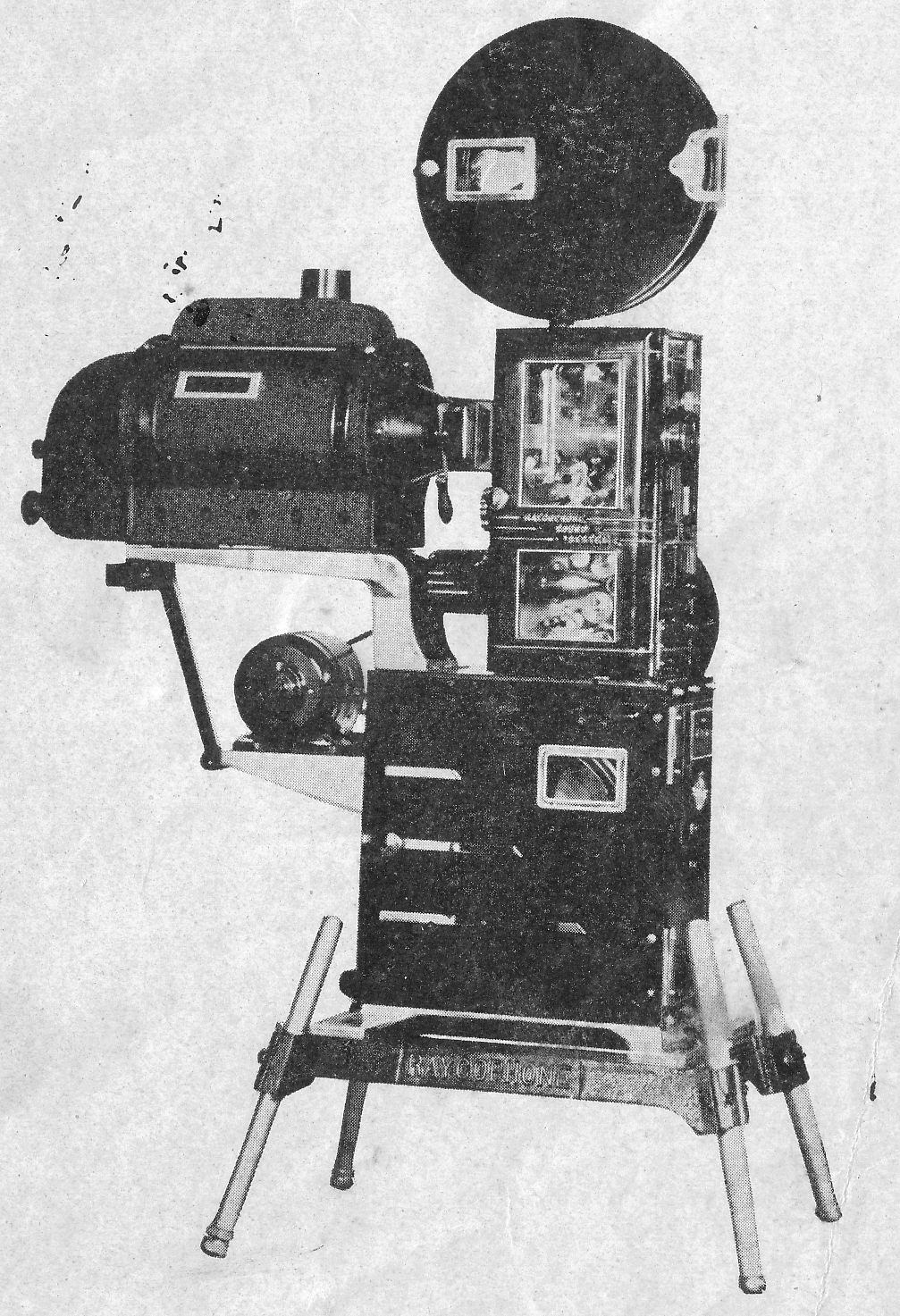
The P6 was introduced 1937
Stand alone projector heads and mechanism only for the Raycophone J3 models
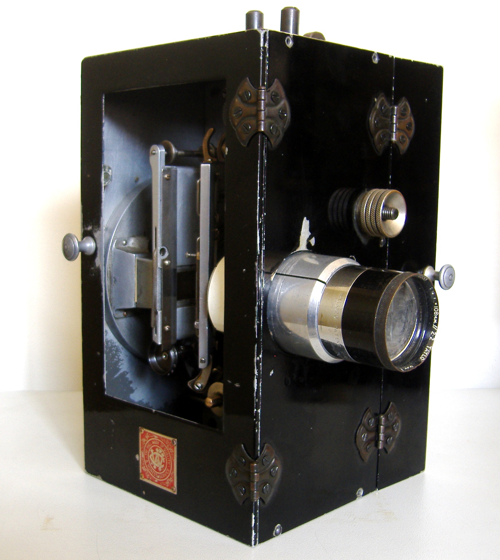
The J3 projector is fitted with a Cummings & Wilson P6 projector head No. 603.
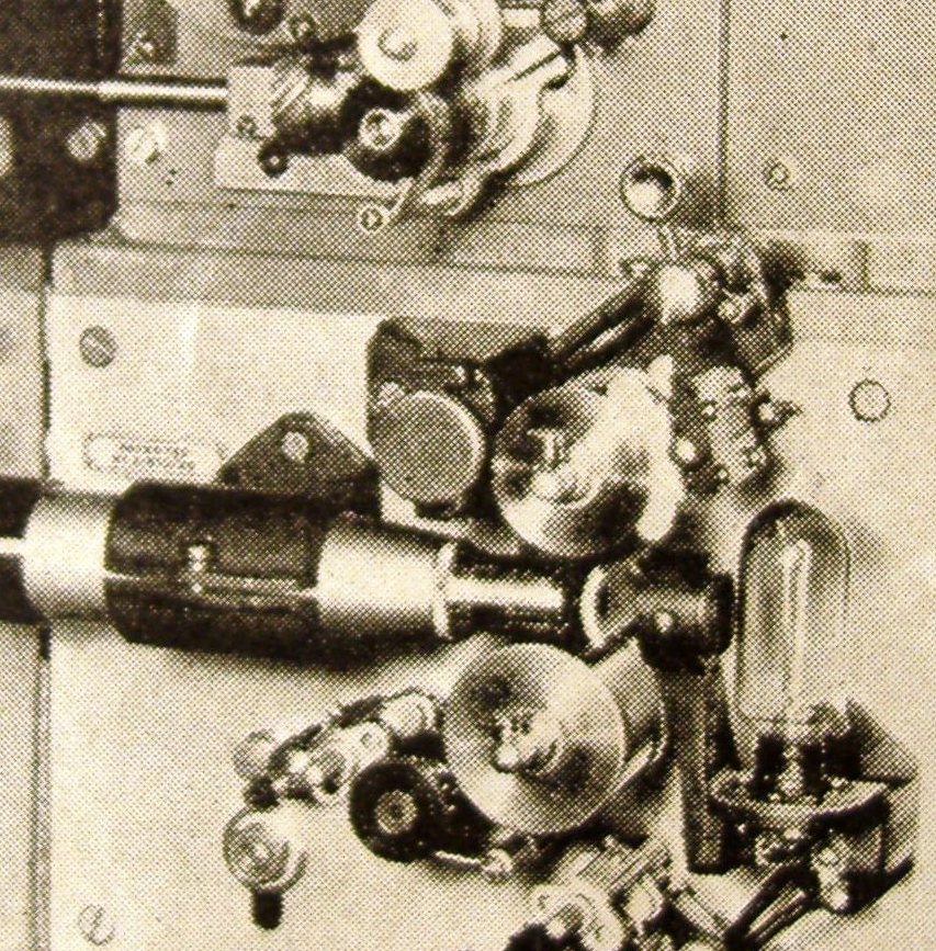
C&W P6 No. 6.3 fitted to Raycophone sound head type 1

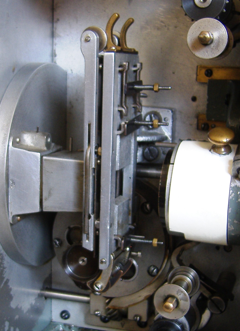
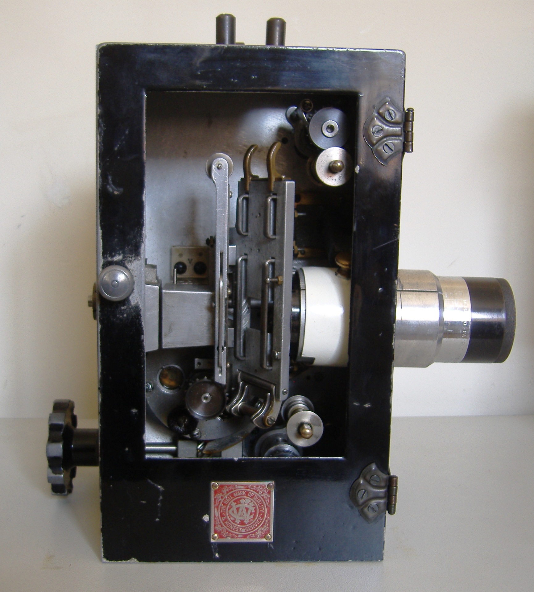
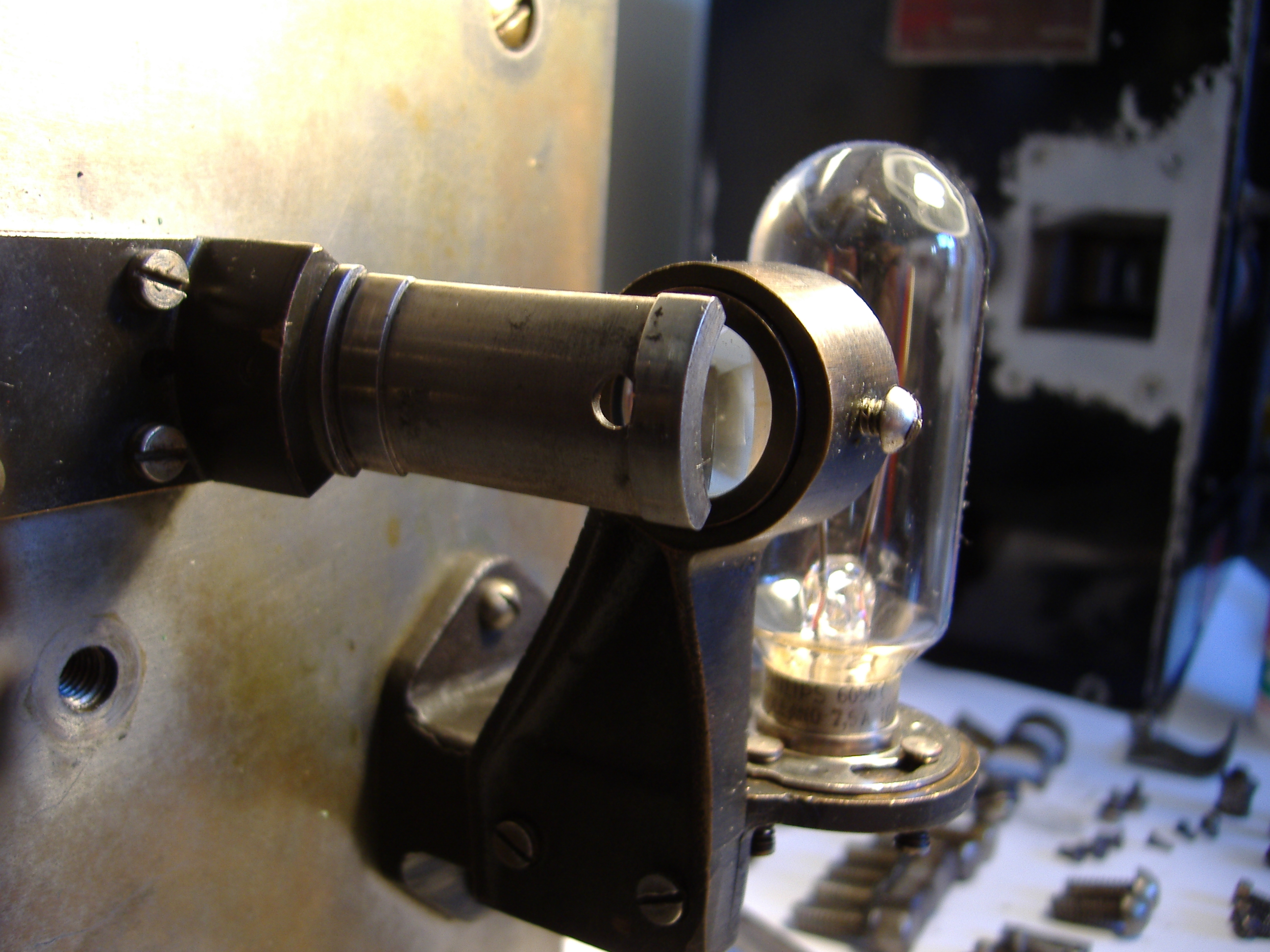
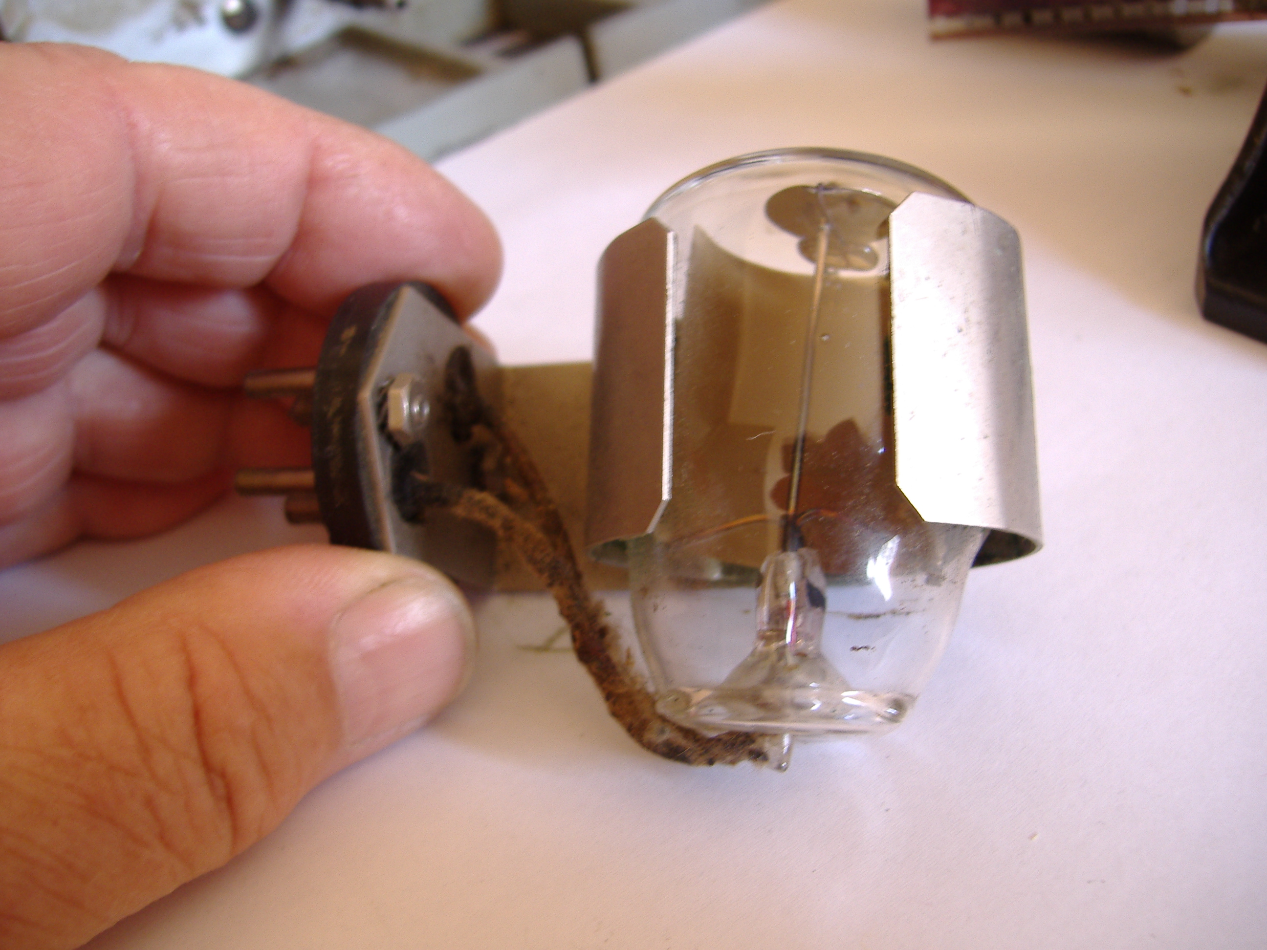
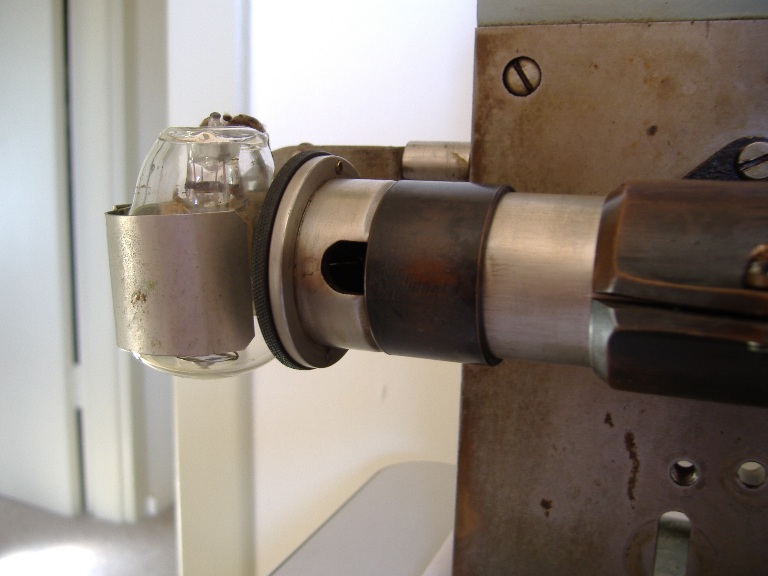
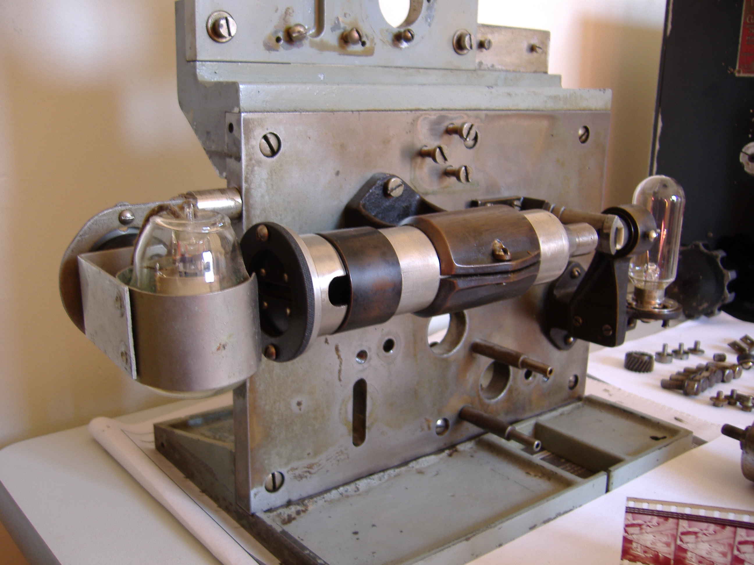
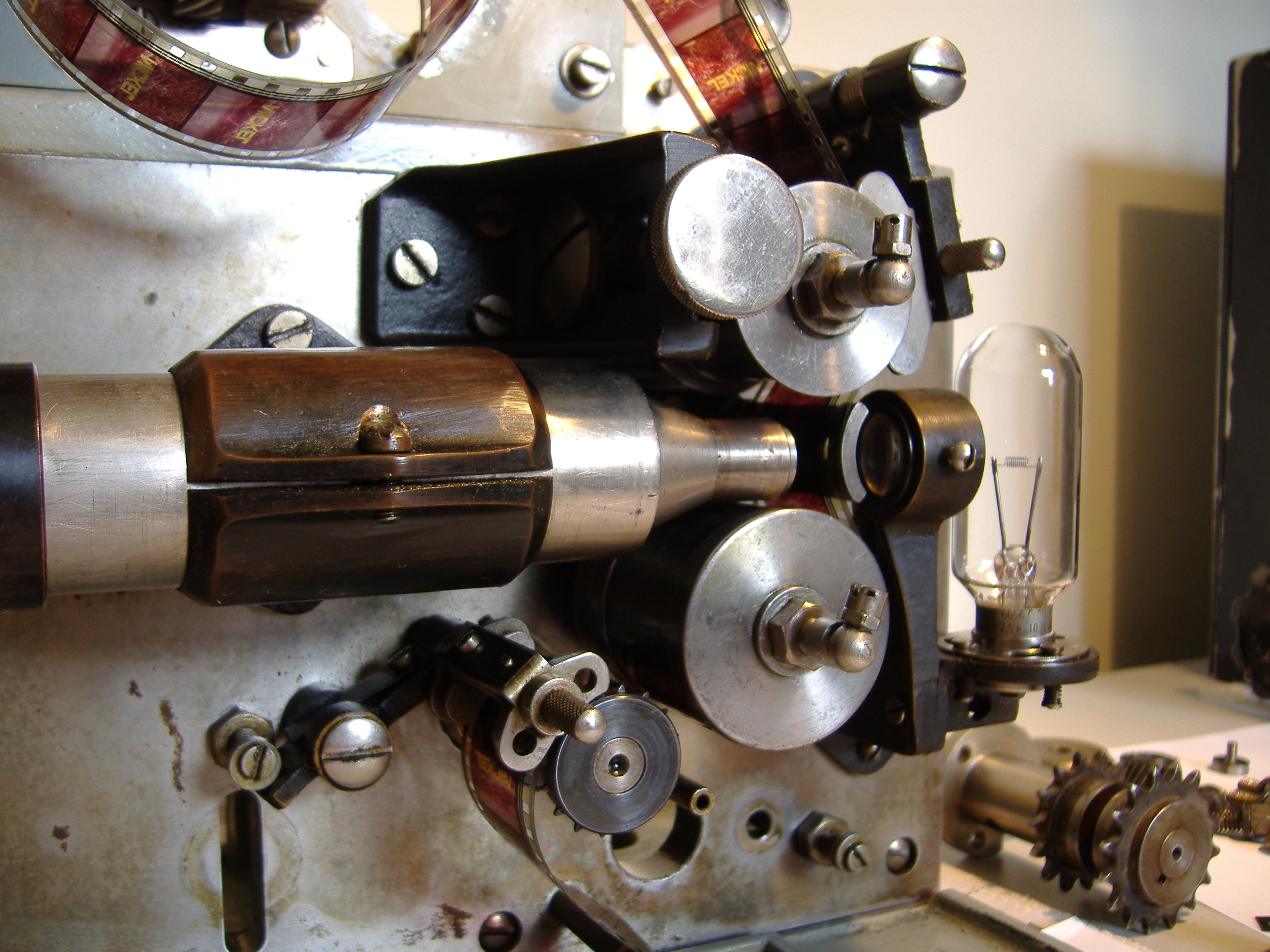
The sound plate is first screwed to the base plate. The exciter lamp holder, the scanning aperture and the optical magnifying barrel are next fixed to the backing plate. The optical barrel and lens assembly at its small end projects an enlarged image of the sound track from the scanning aperture to the scanning slit.
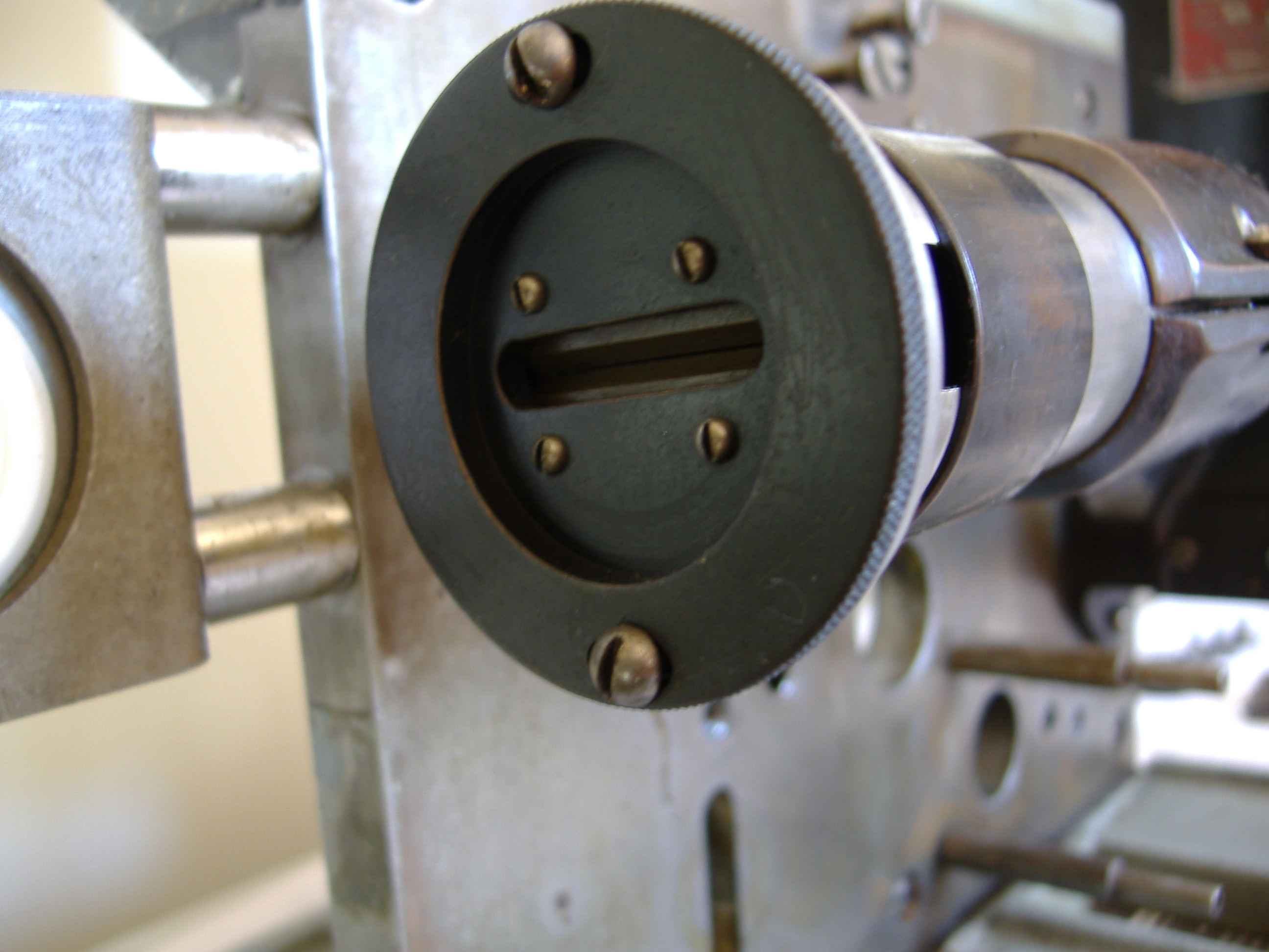
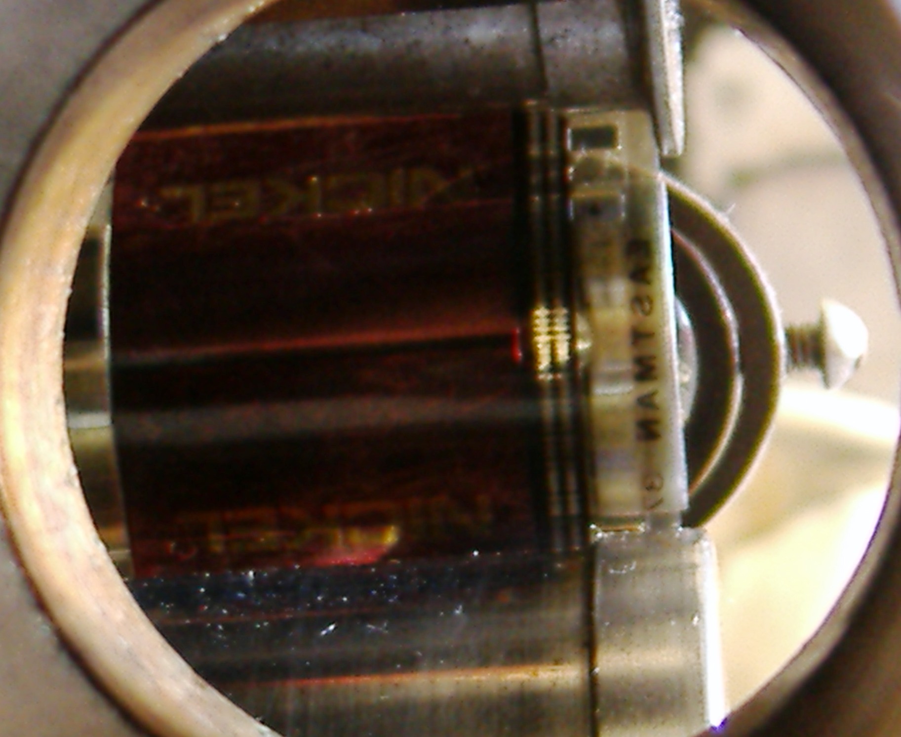
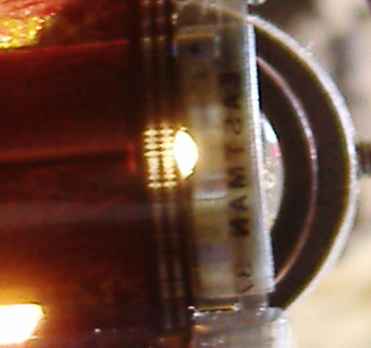
The dark coloured band covering observation port at the slit end of the tube can be slid away to enable accurate focusing of the sound track on the scanning slit.
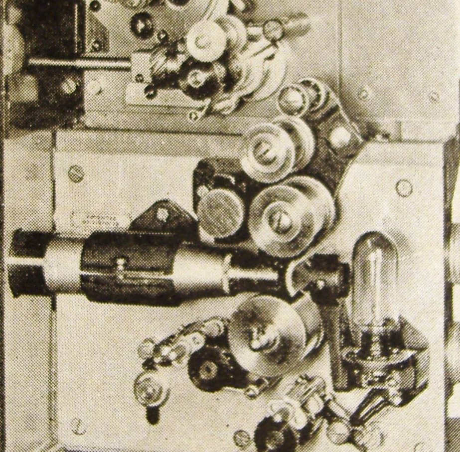
The three screws at the top of the plate are the fixing position of the roller assembly
The system, when correctly adjusted, focuses the actual sound track’s emulsion grains, putting the film base out of focus. This much improves the frequency response of the sound track.
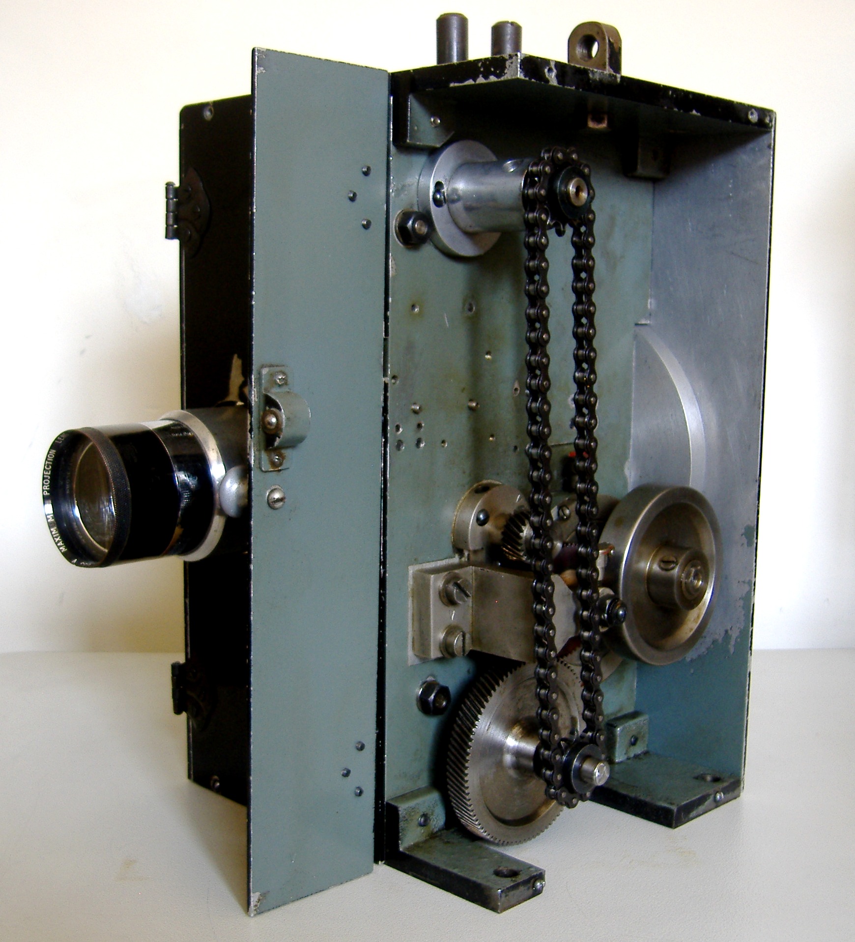
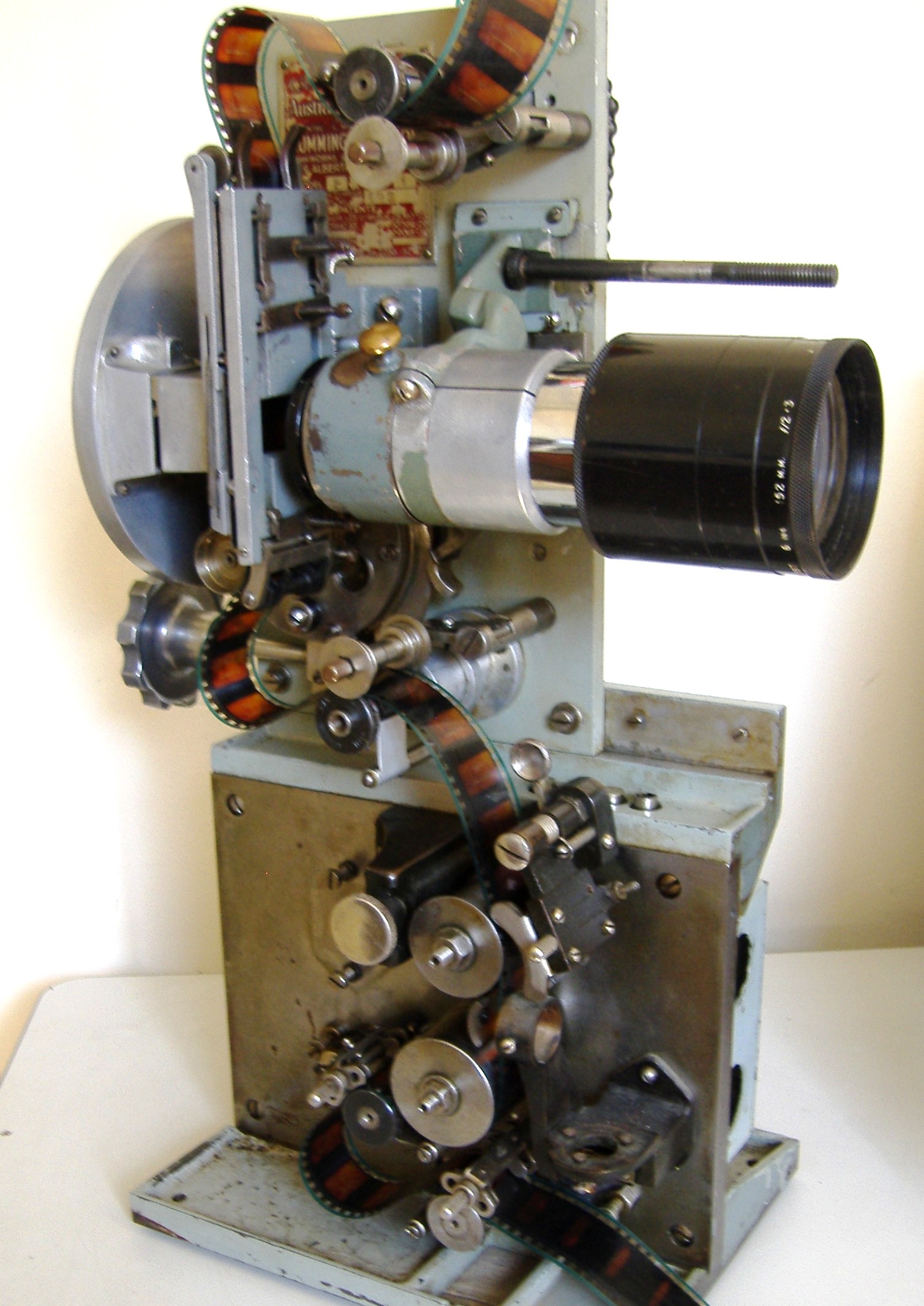
The angle bracket and projector main plate is now attached to the top of the sound head.
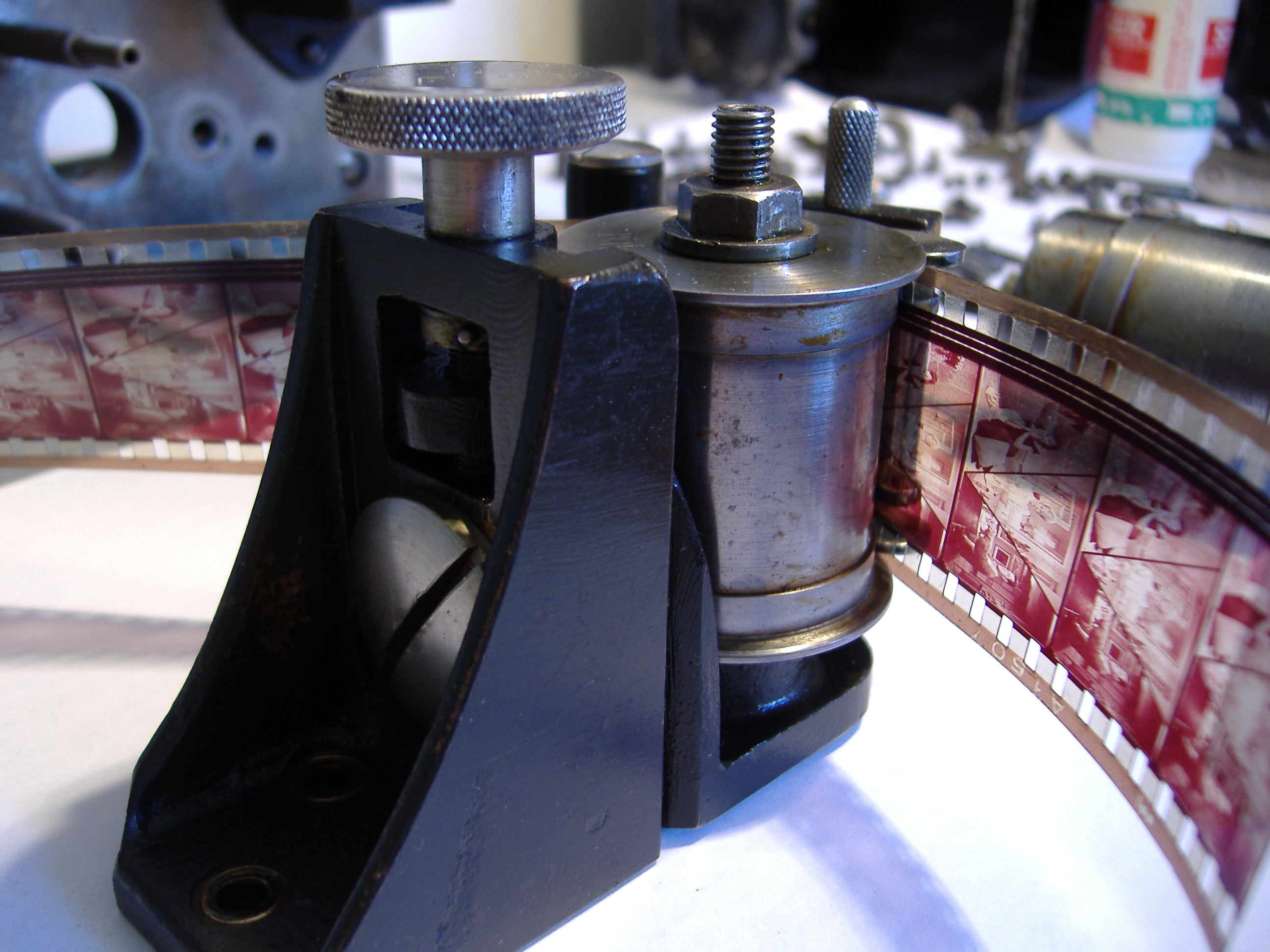
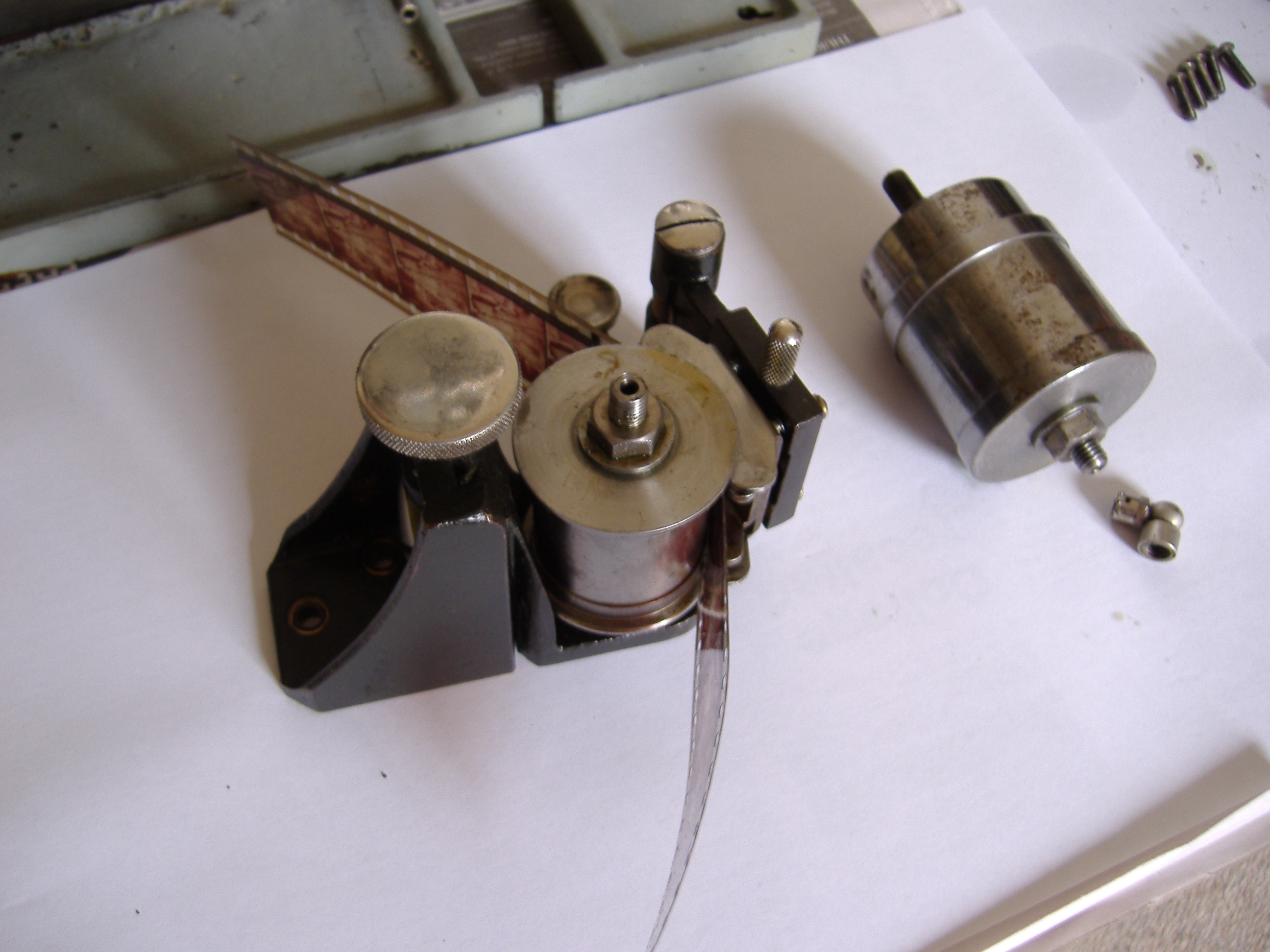
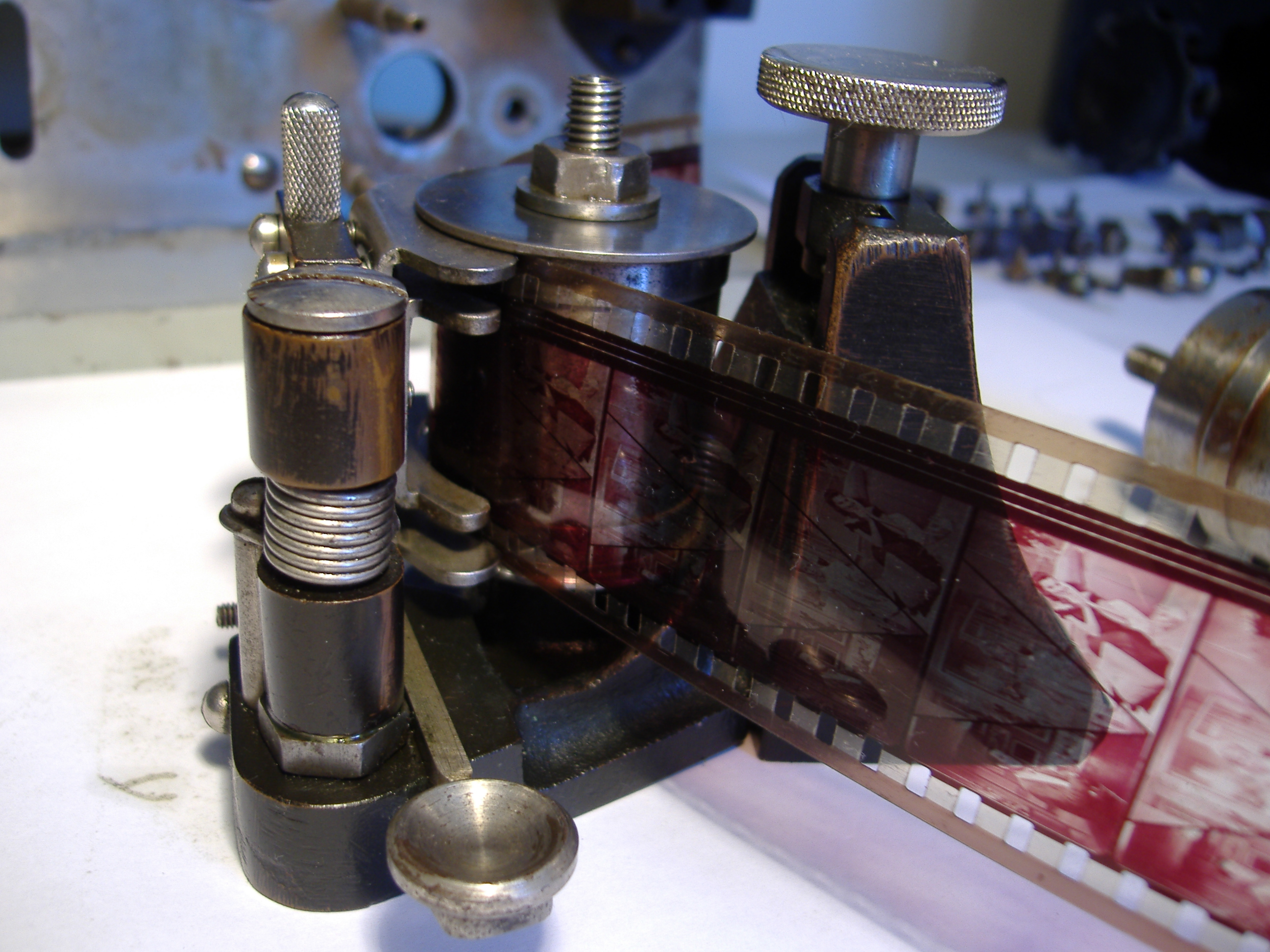
Both rollers are free wheeling and their movement is independent of the main drive shaft. They are driven by the film passing over them. The lower sprocket and shaft provides the driving movement for the film through the sound head. Add light oil to the roller oil cups and spin them to check for free movement. This picture shows the main sound shaft already installed and piece of film loaded to check the movement.