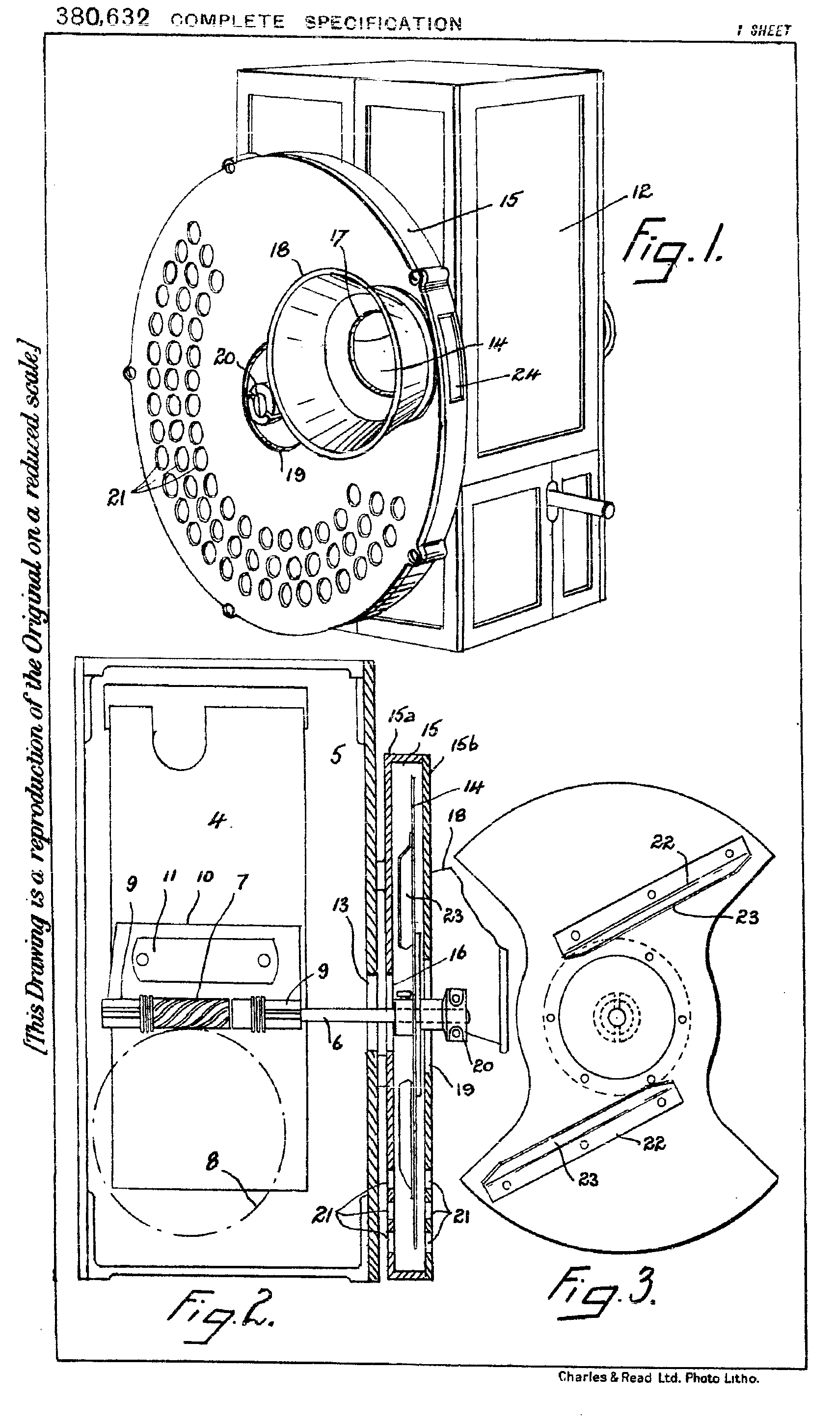
The Cummings & Wilson Model E. This article covers photographs of models and assembly of the Model E.
Taken from The C & W Manual written up by Richard Ashton.
Other articles on the C & W projectors are also written up in detail.
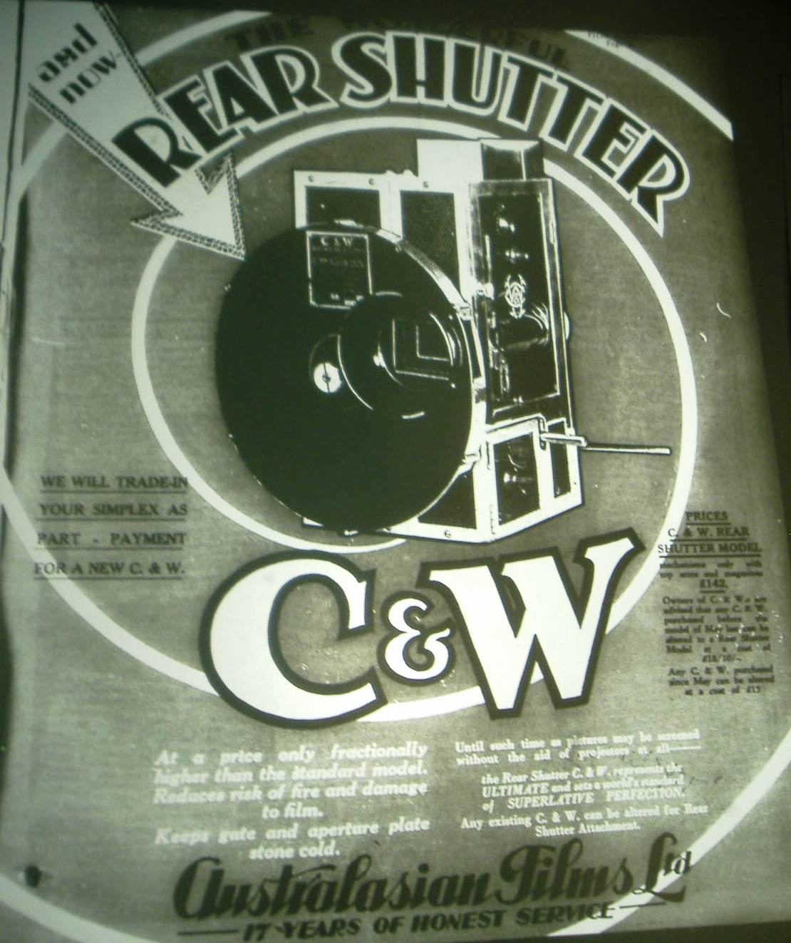
This advertisement of November 26 1931 shows that conversion of model D’s and earlier models could be made for £18:10
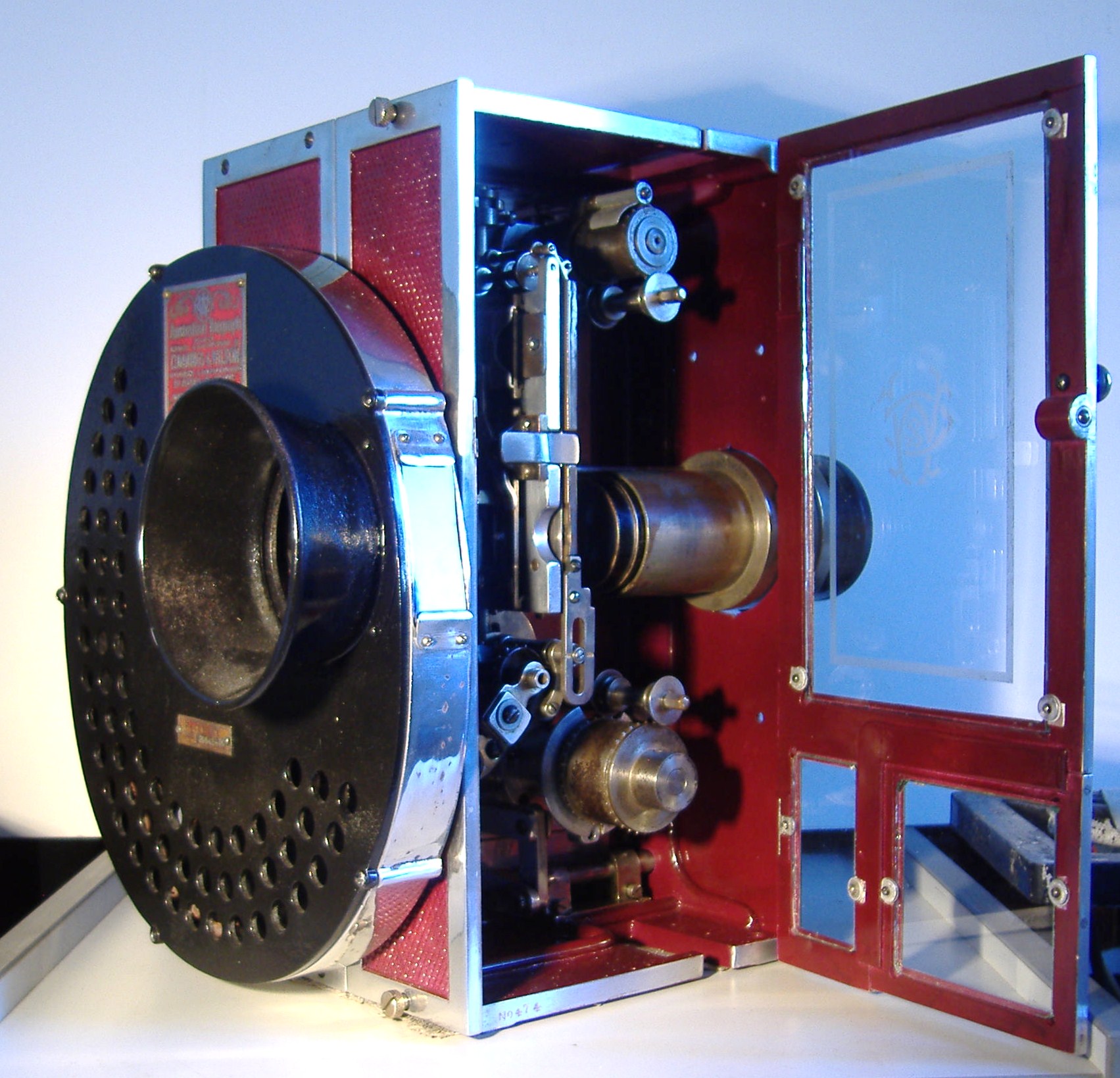
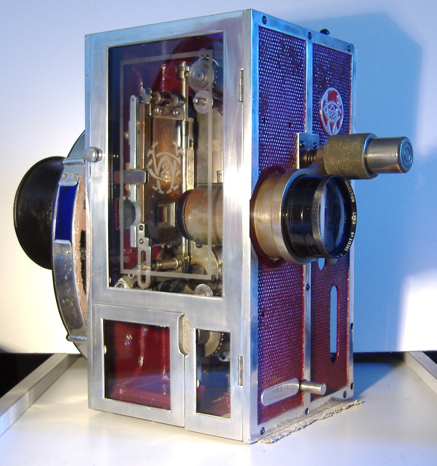
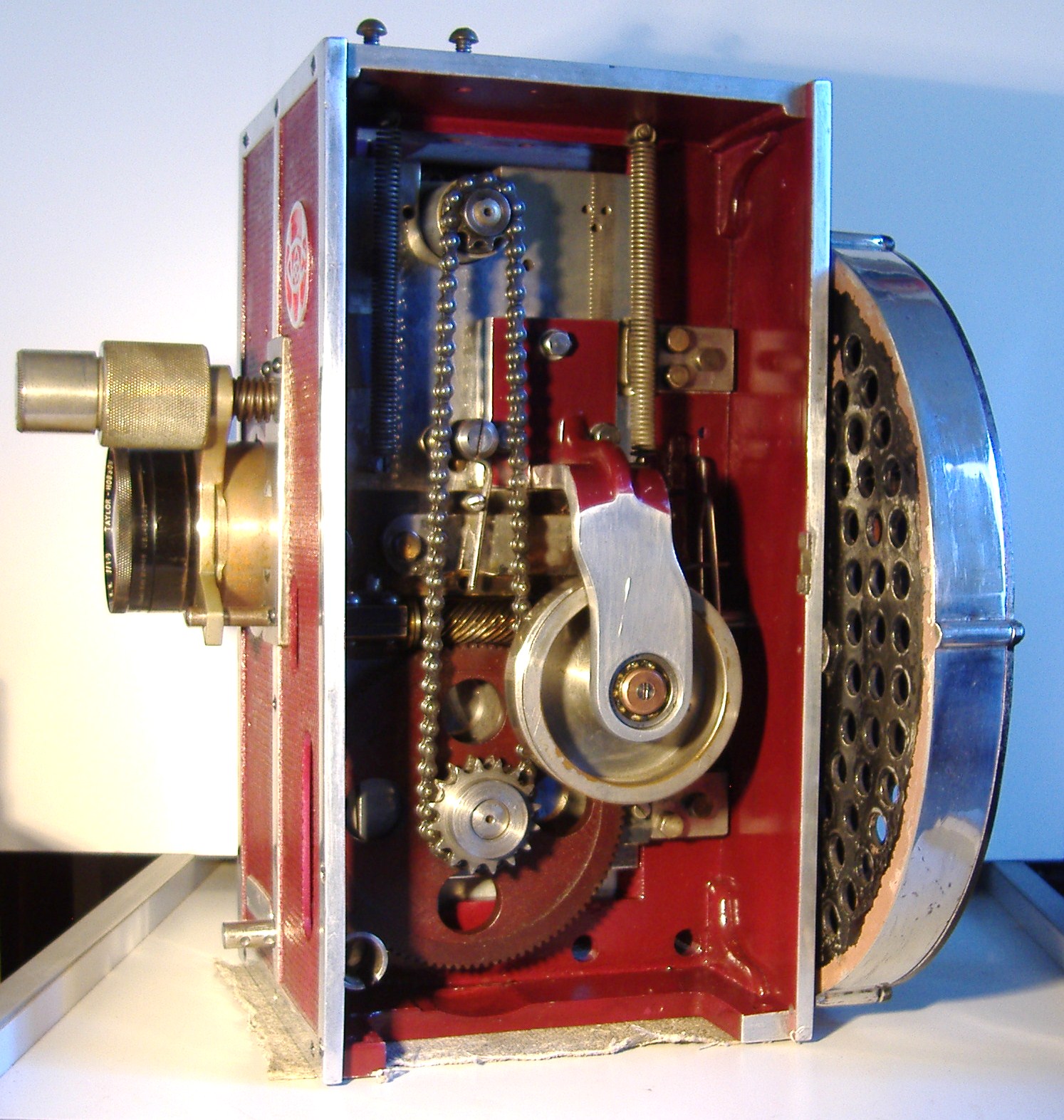
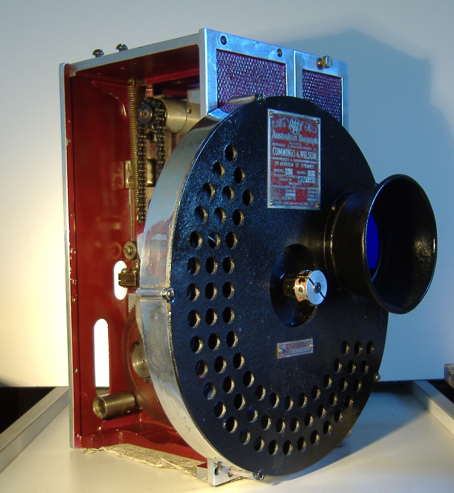
C&W Model E Rear Shutter Picture Gallery
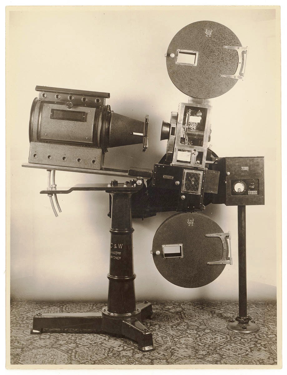
The original price for the new Model E was £142 projector and top spool box
The sound head is Western Electric including a separate pre-amp box and stand, Arc lamp is Hamilton and Baker, the Pedestal and bottom take up spool box C&W
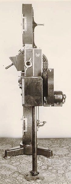
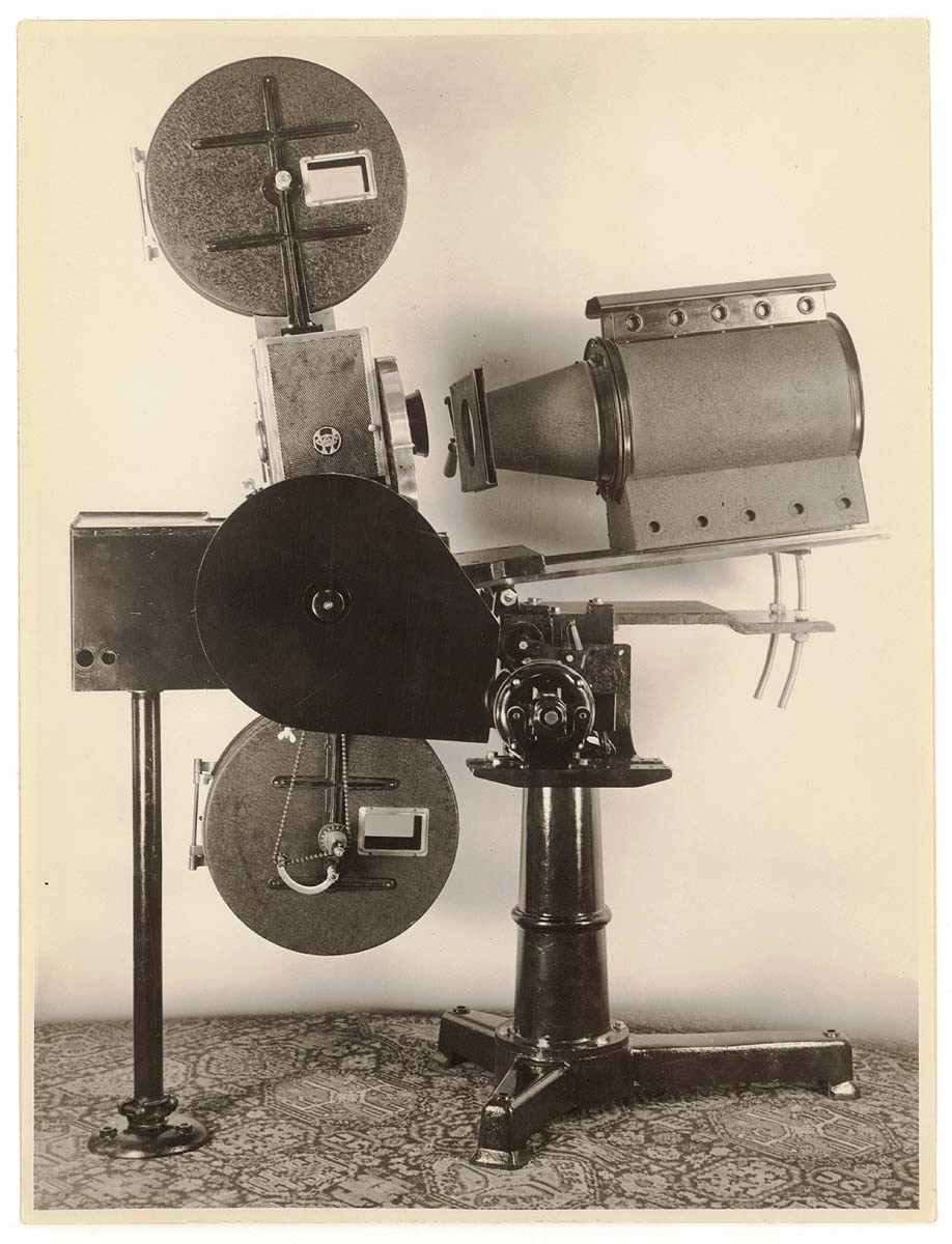
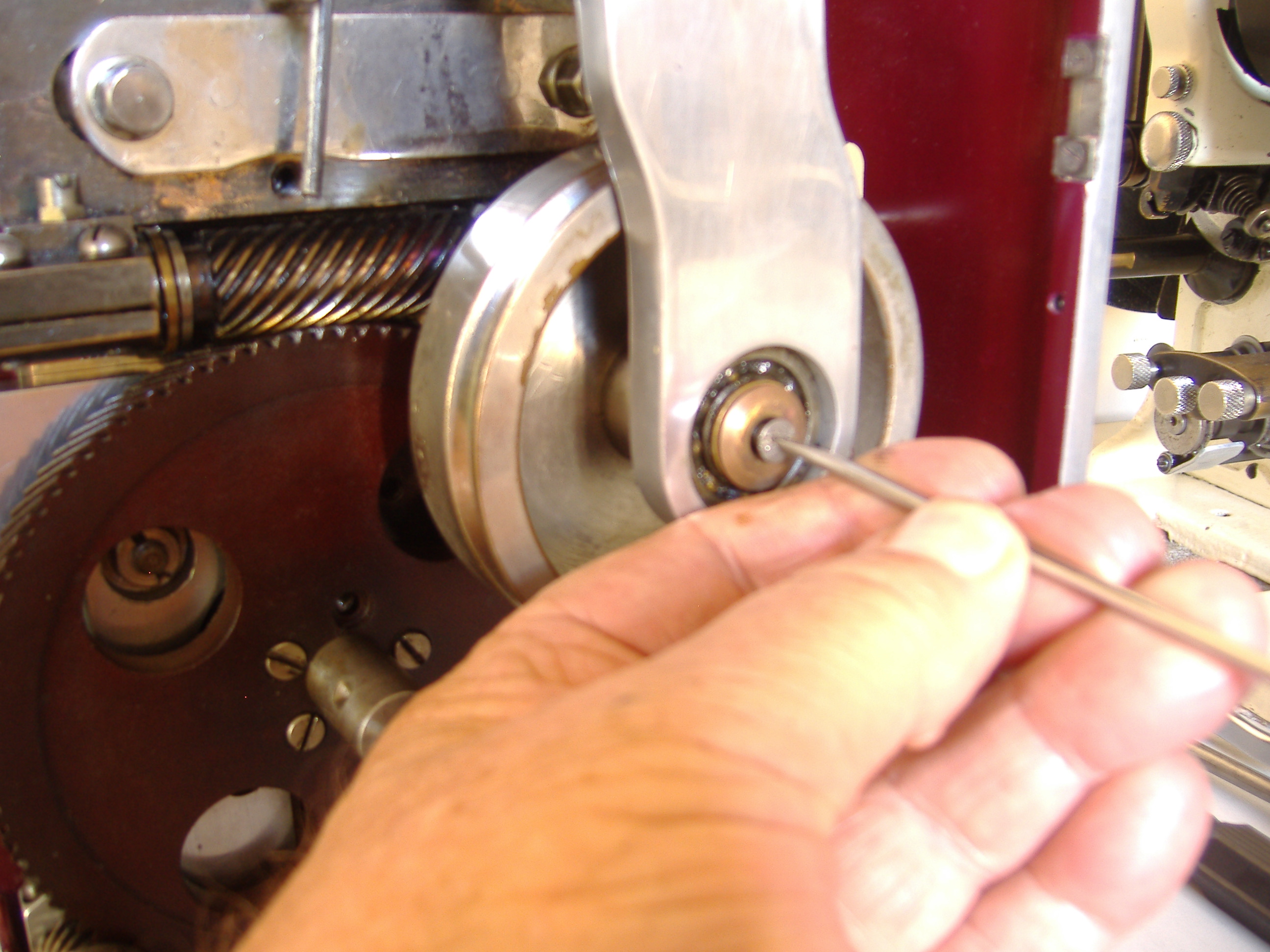
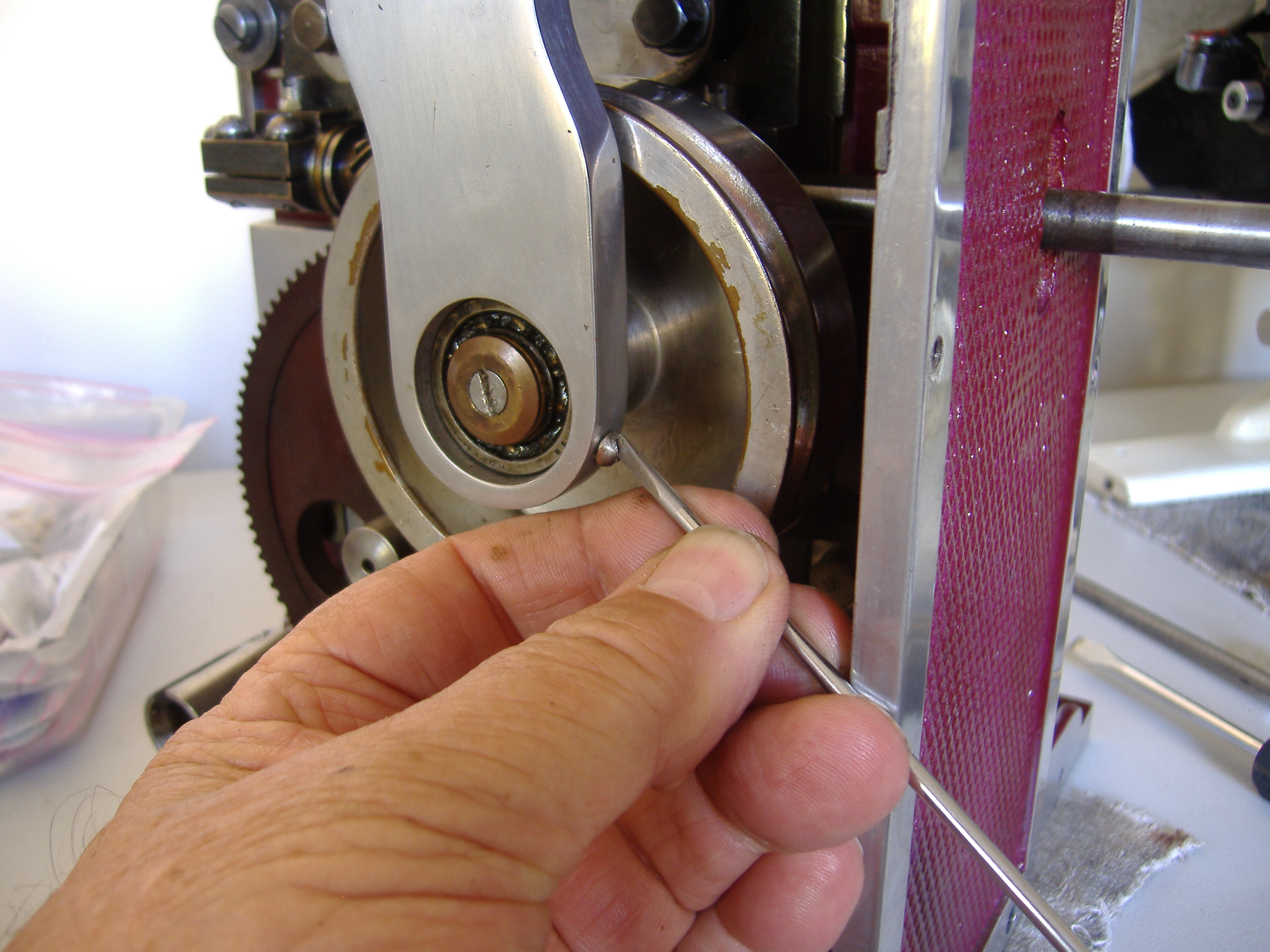
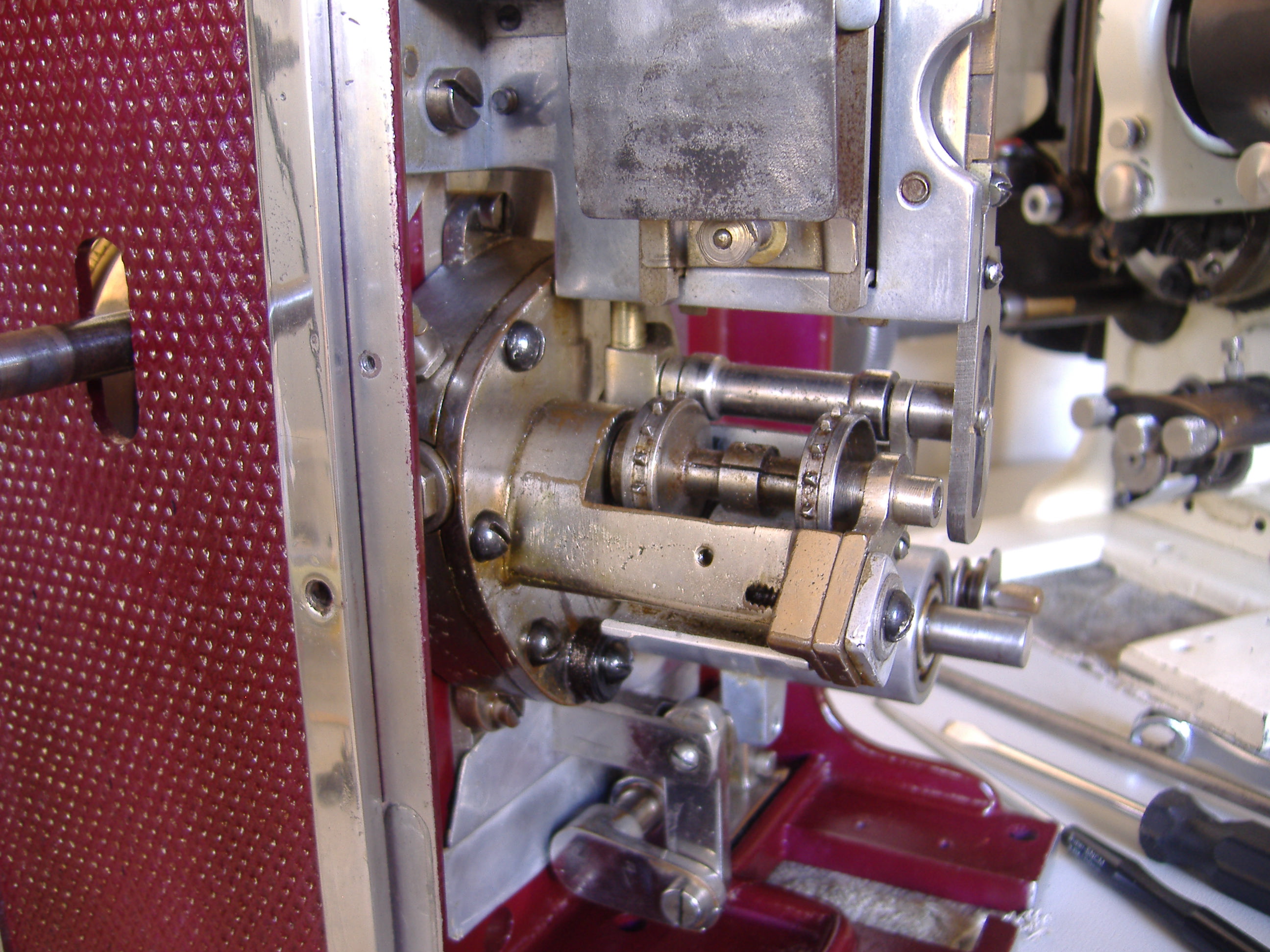
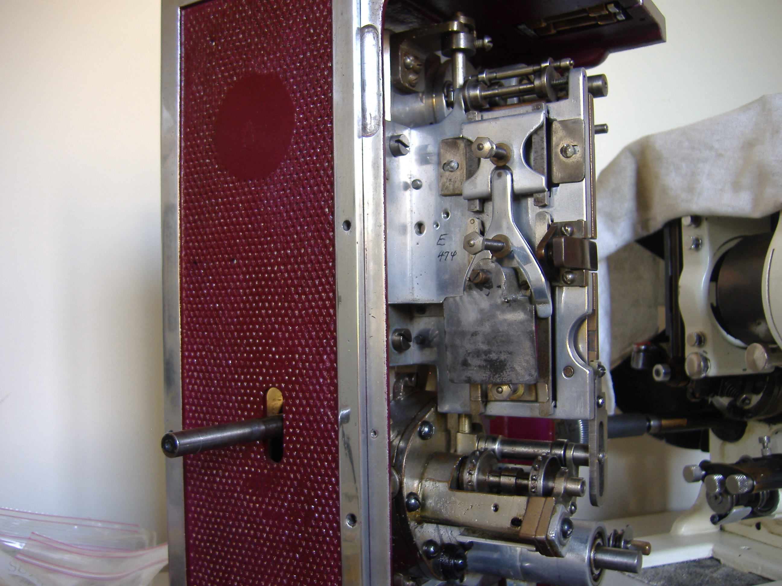
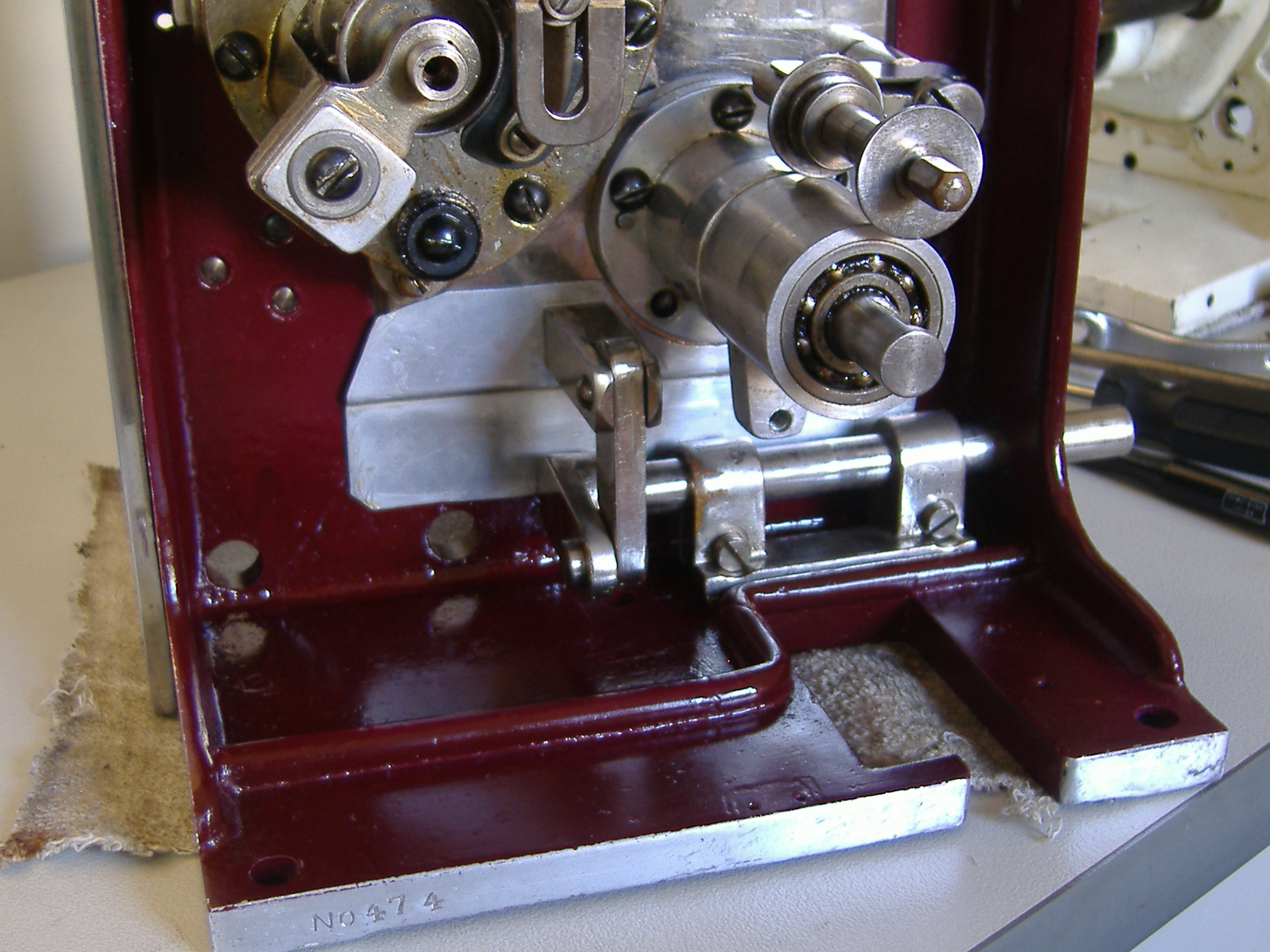
C&W Senior model E No. 474
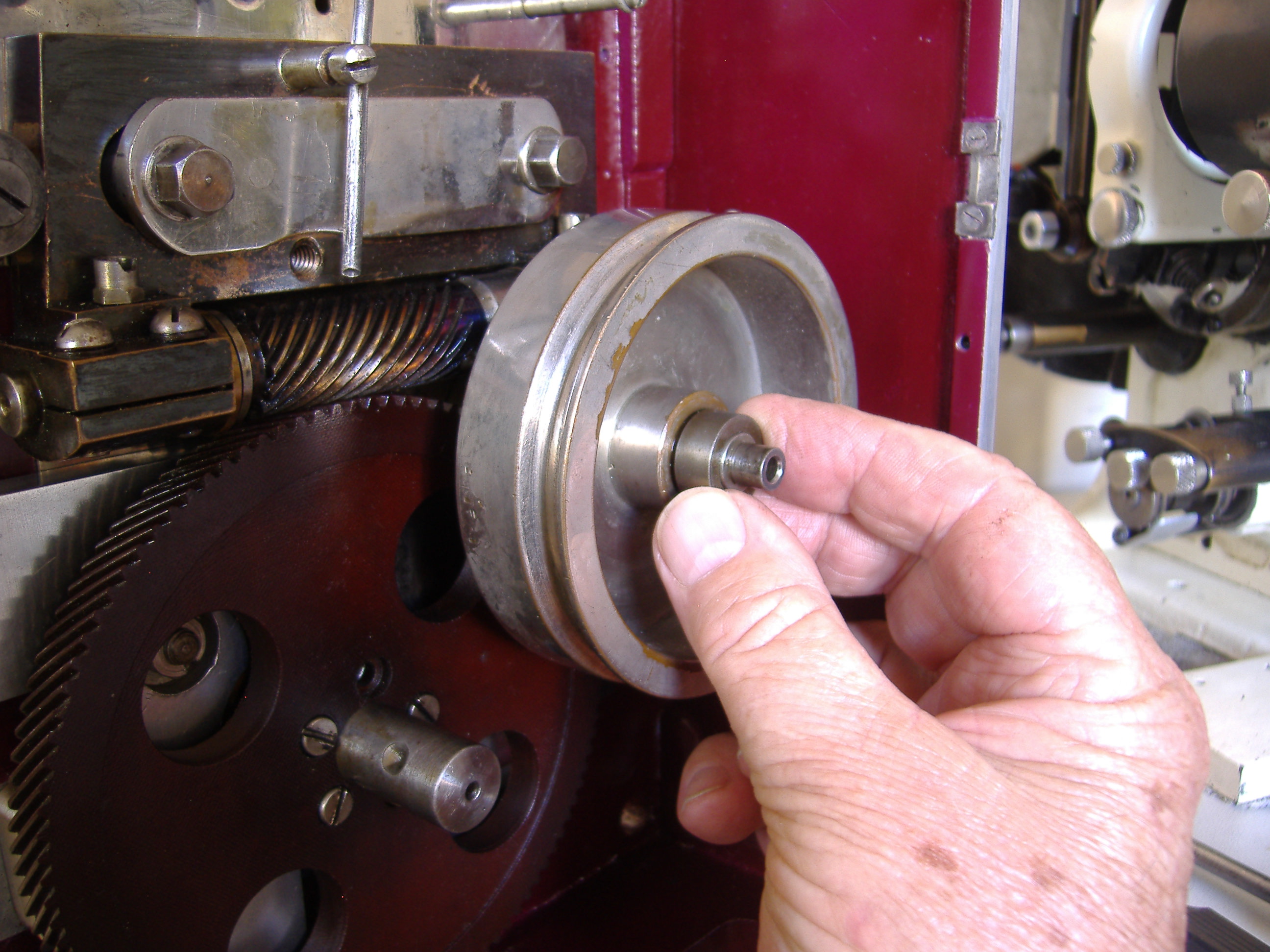
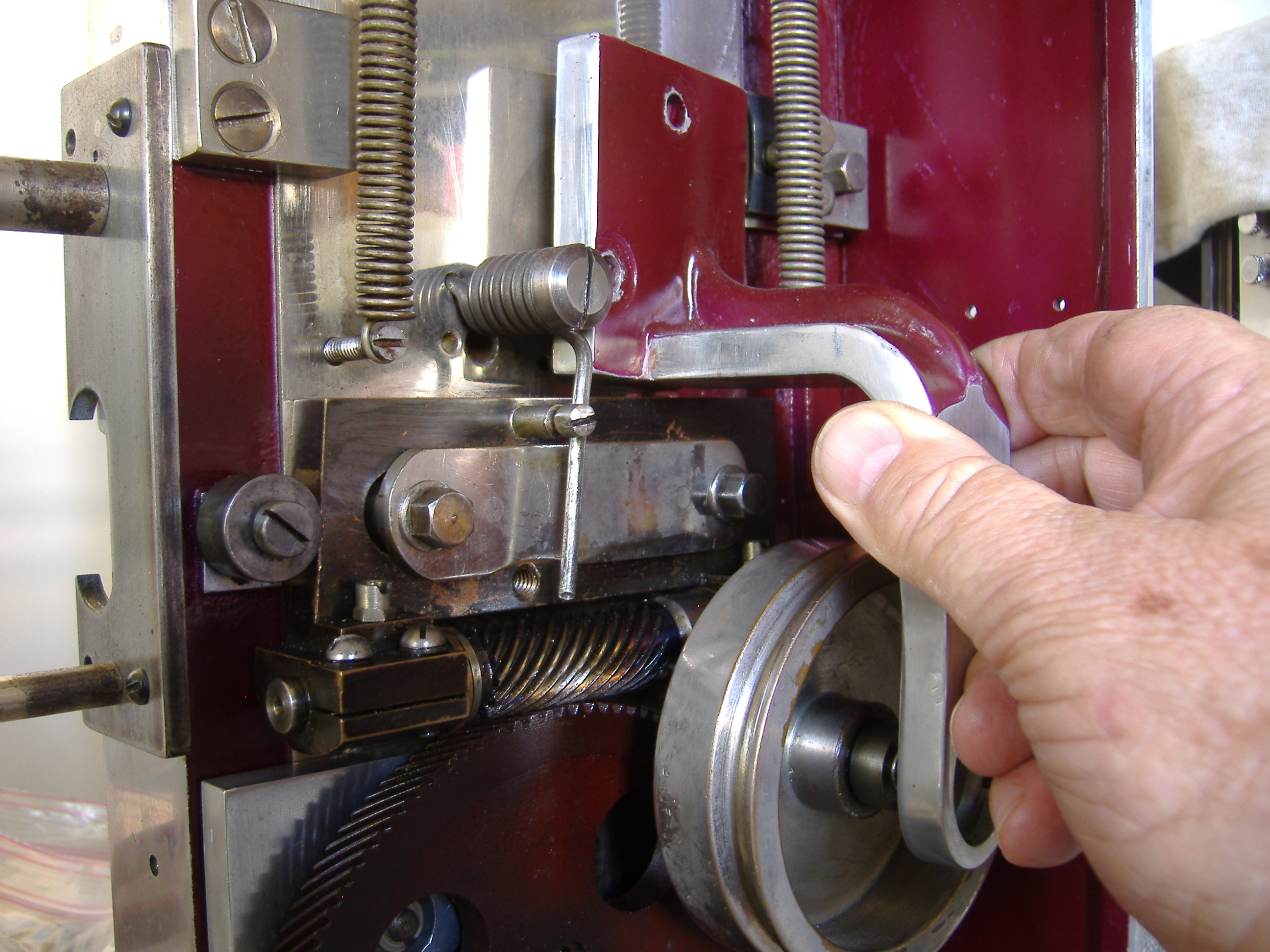
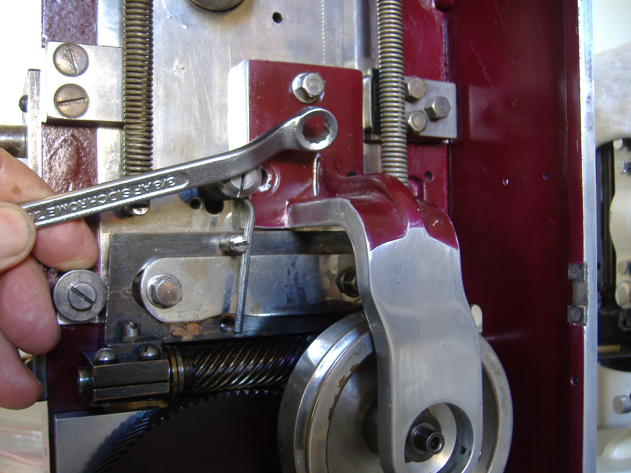
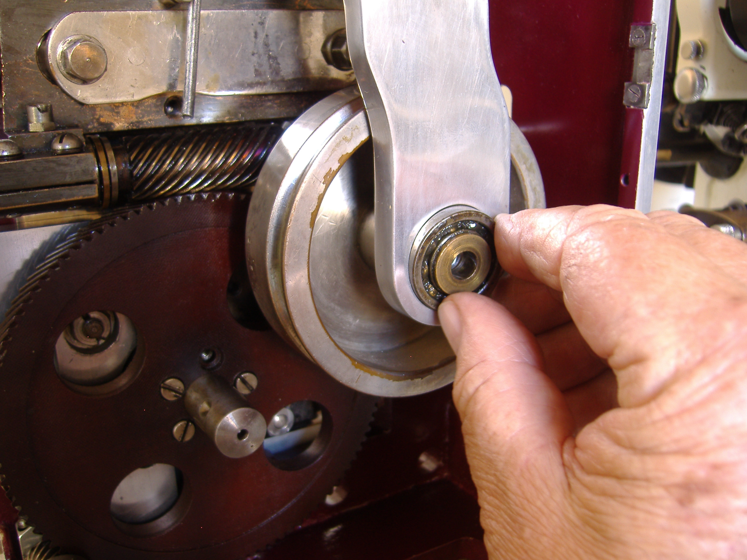
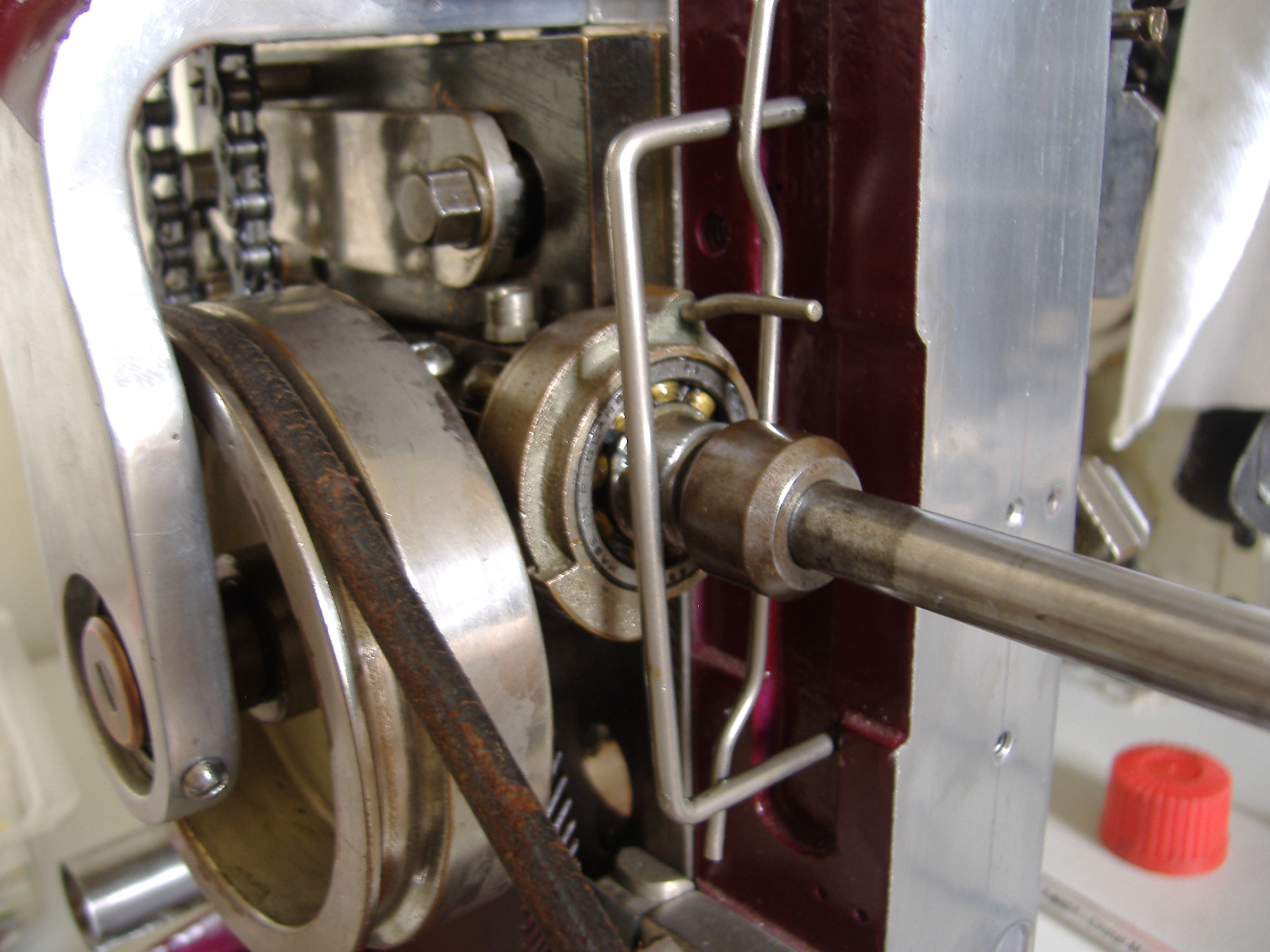
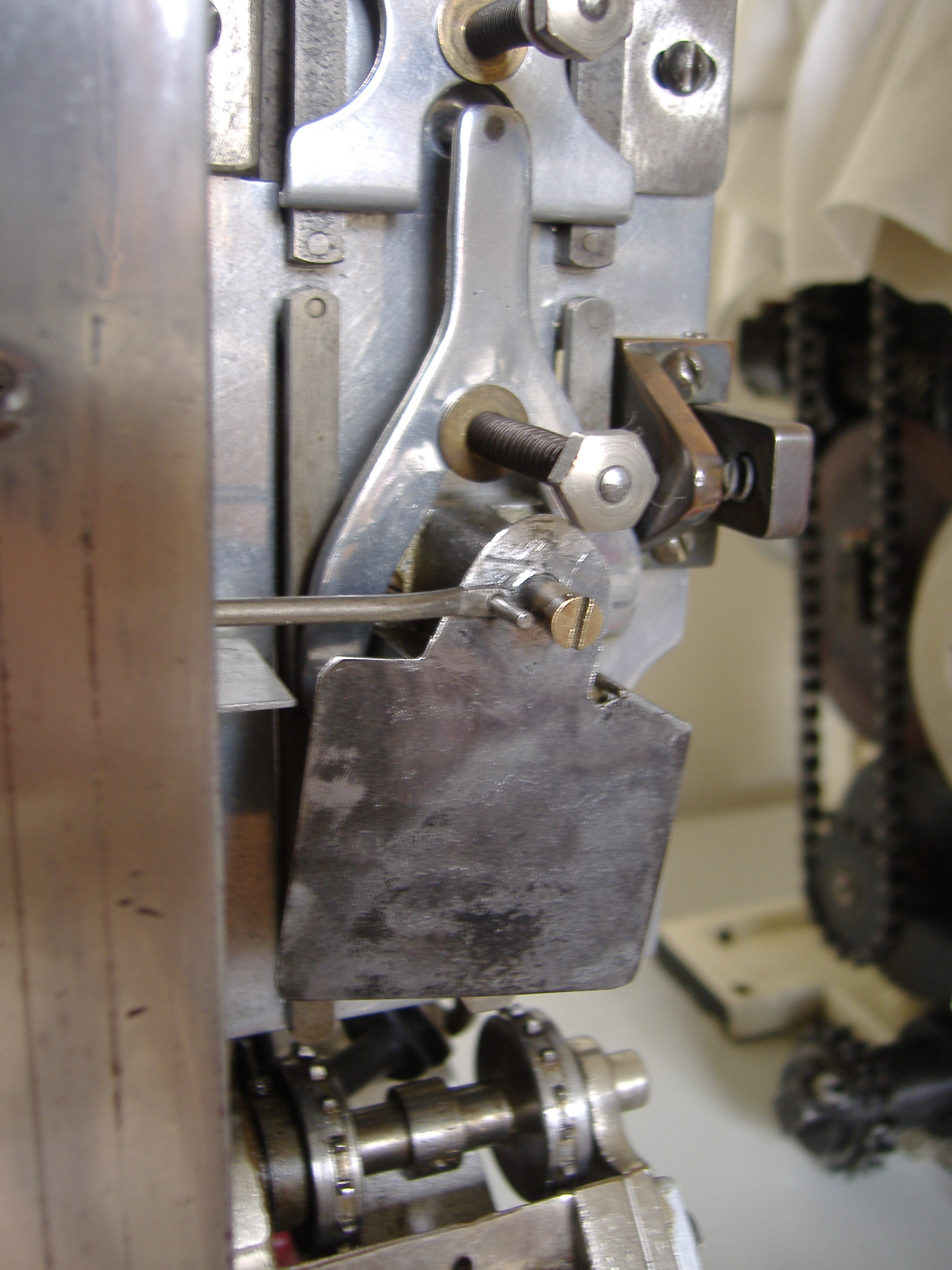
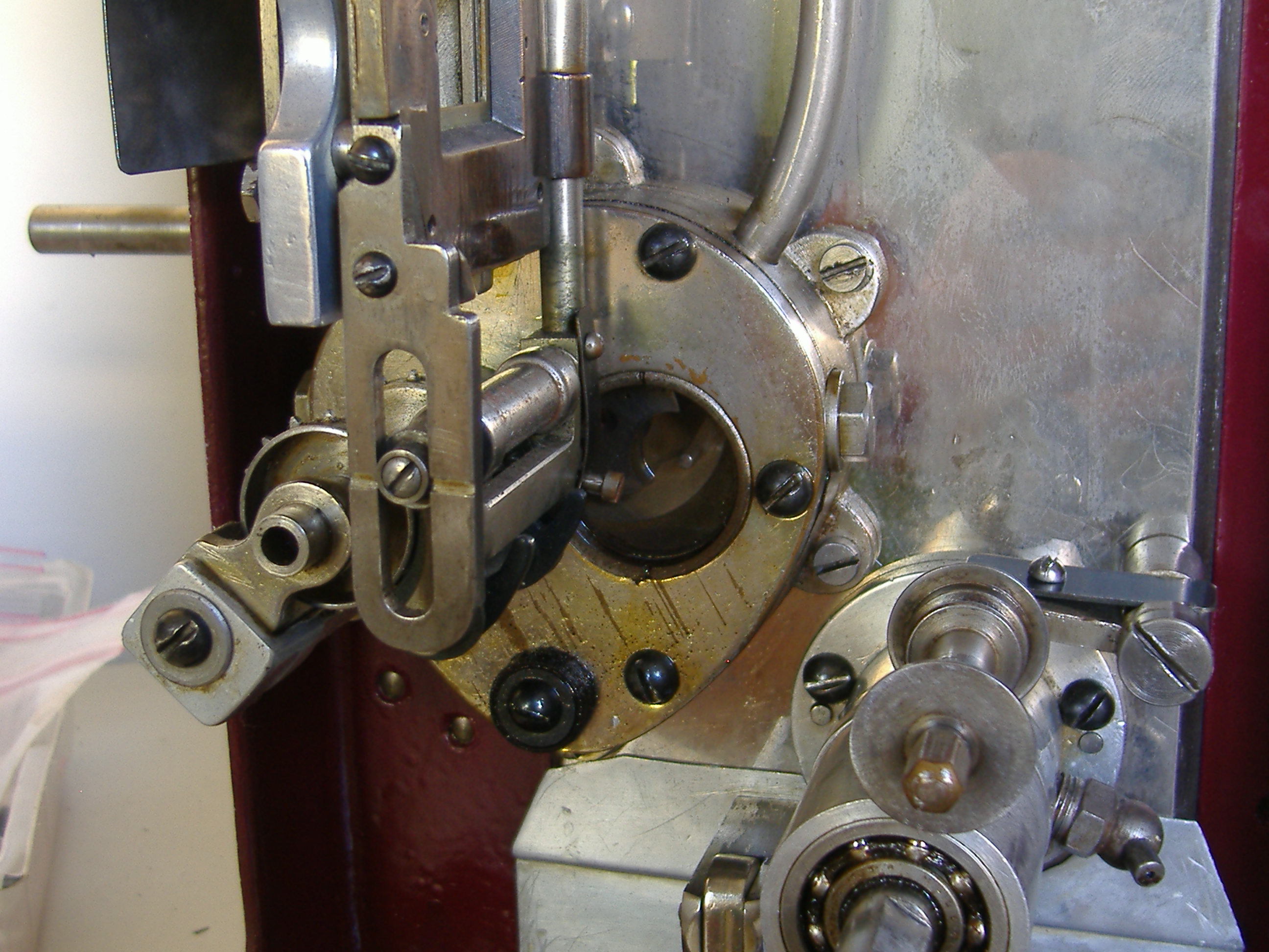
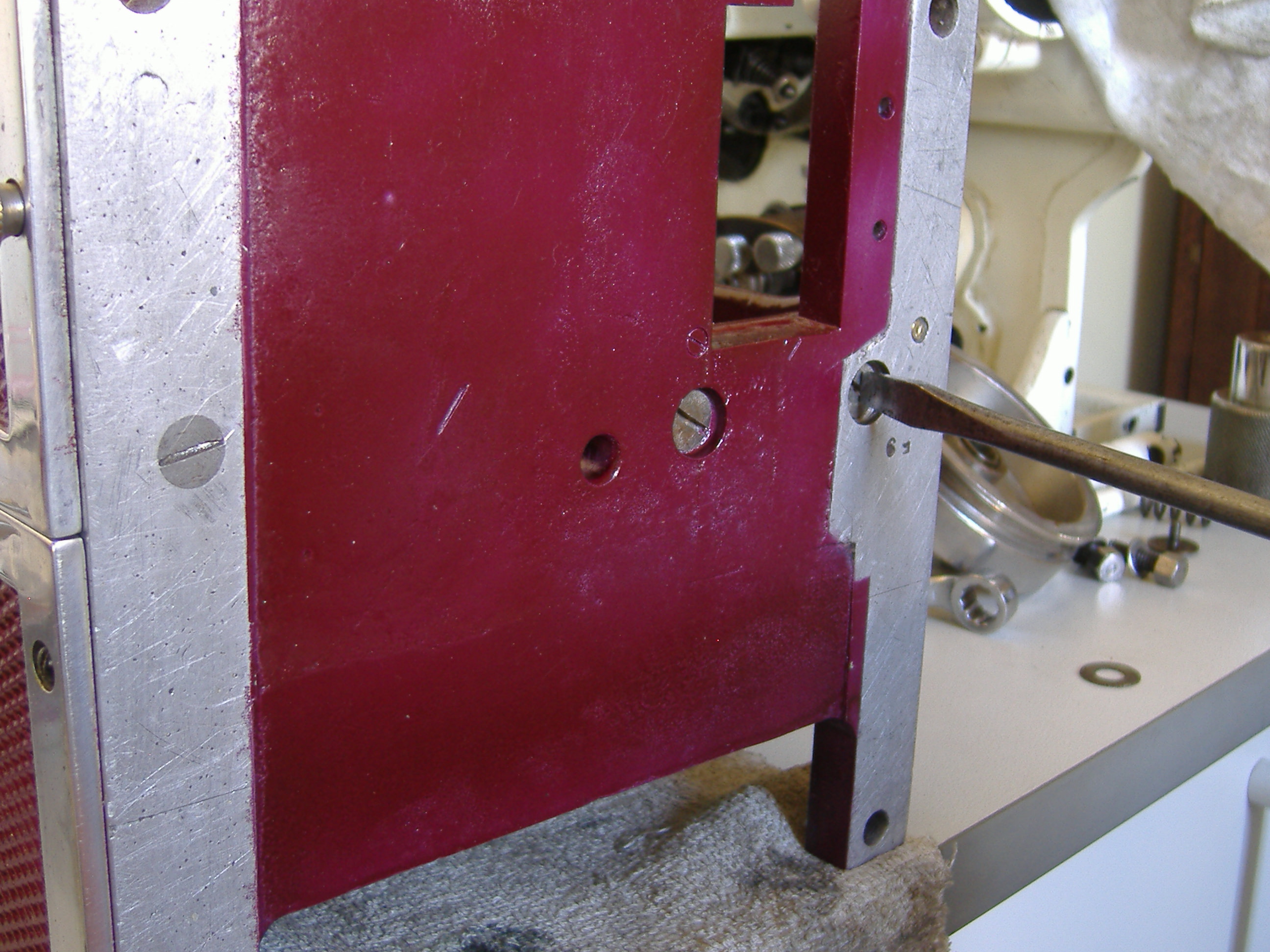
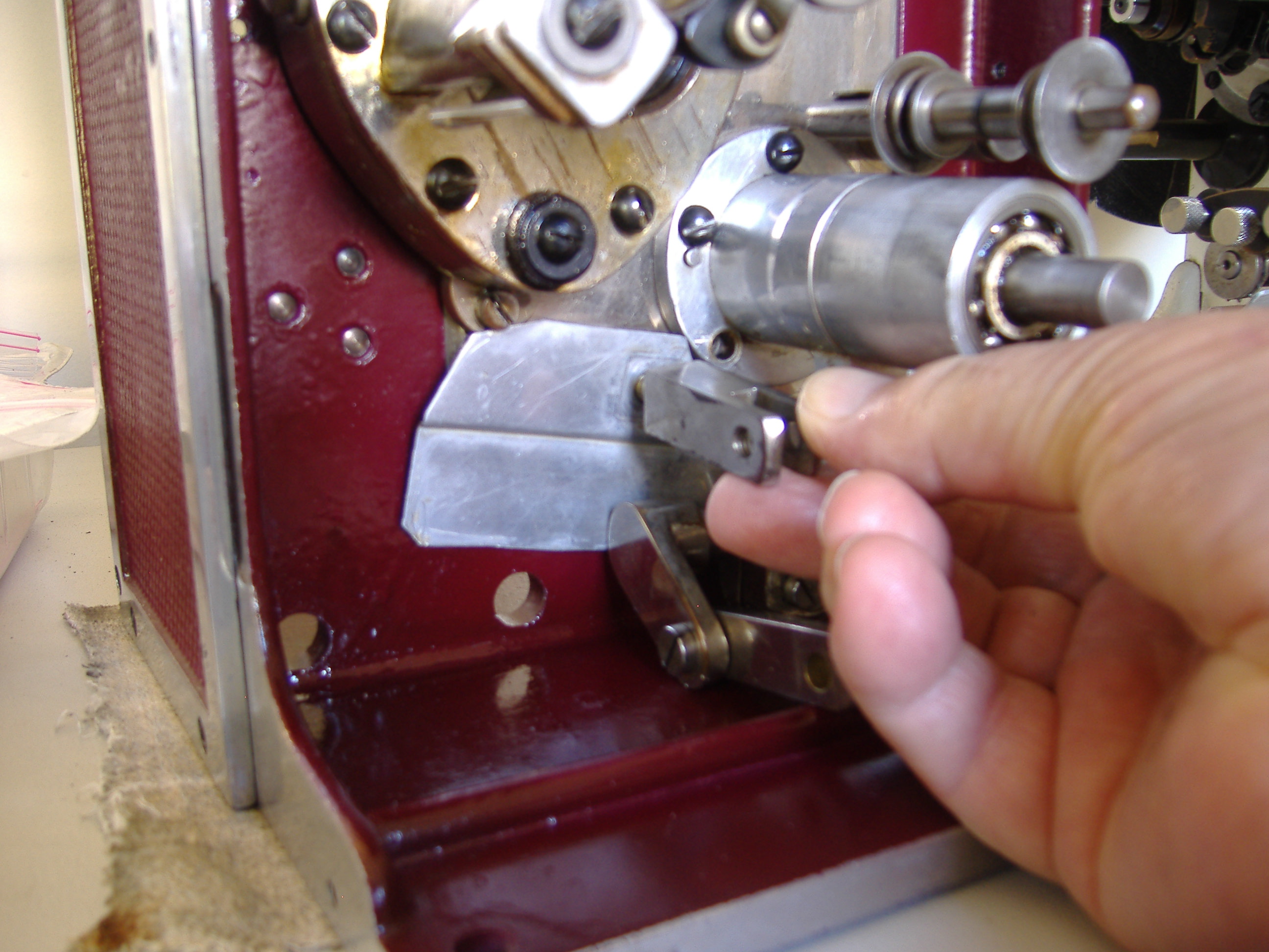
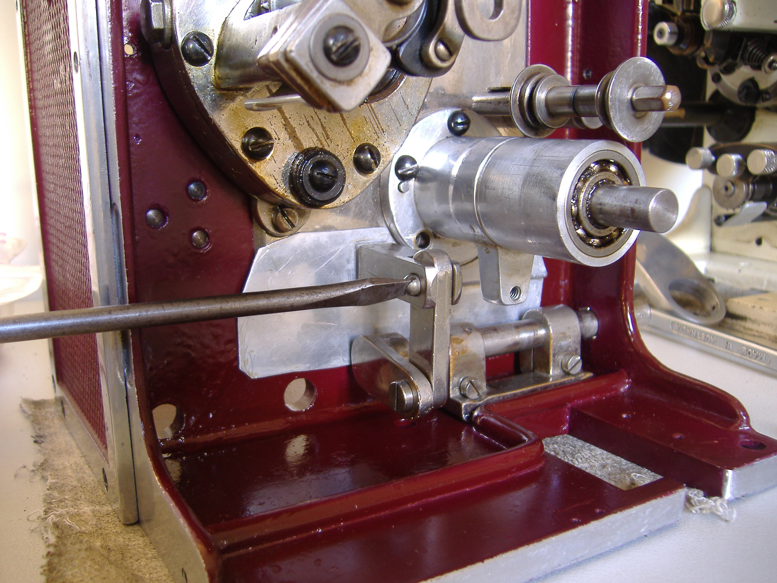
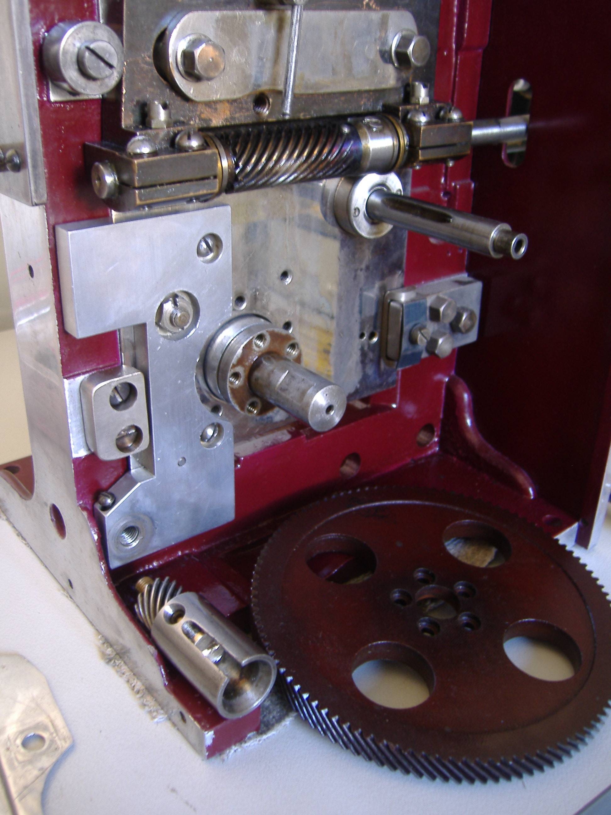
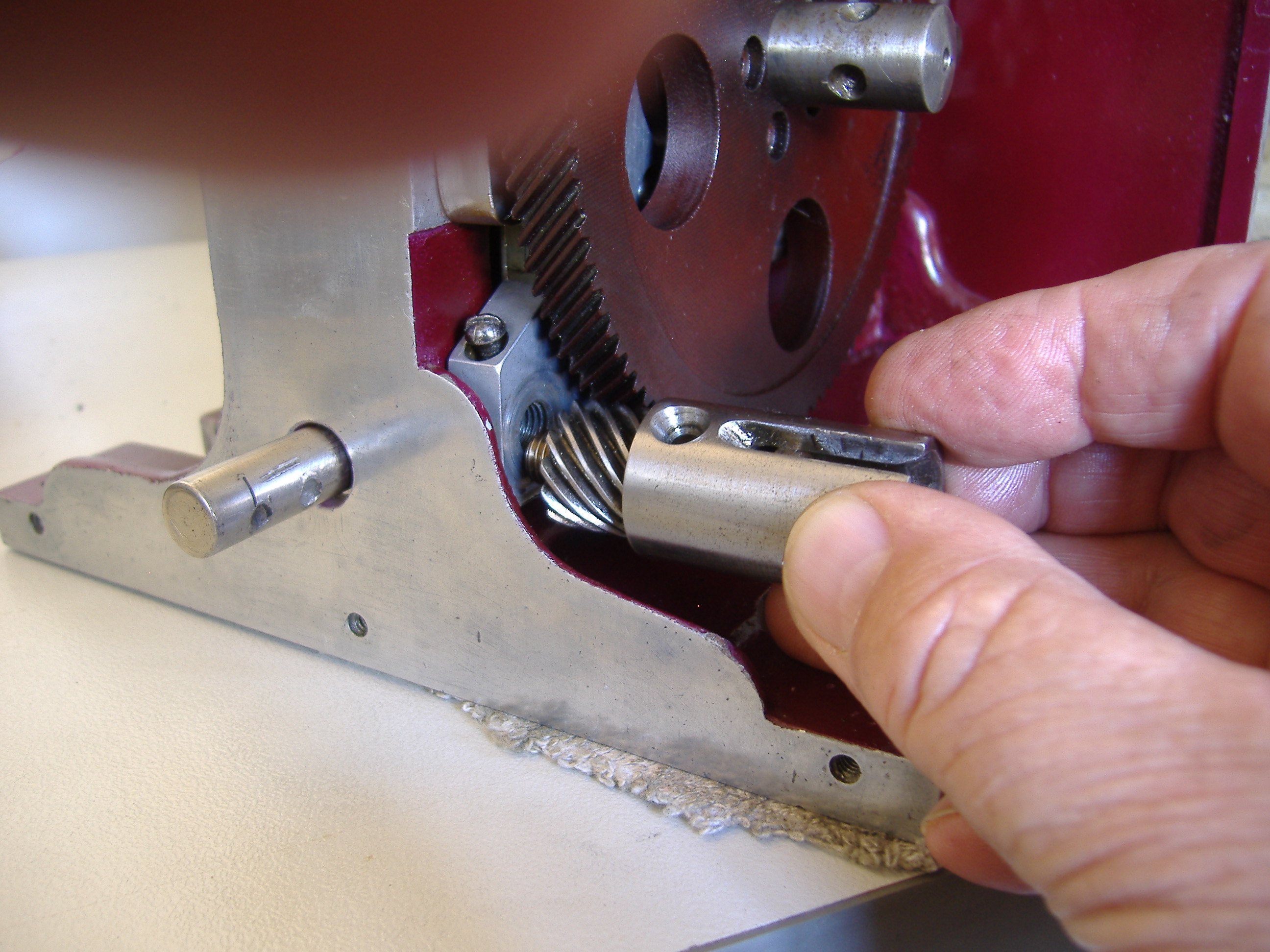
Assembling the Model E
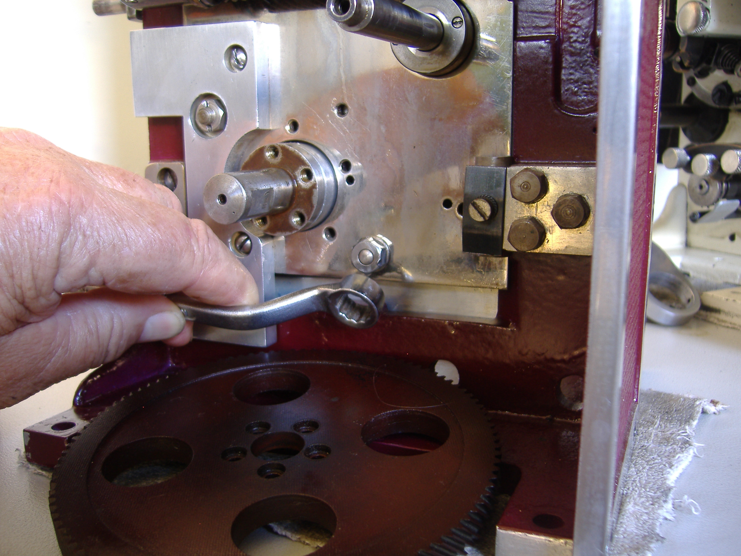
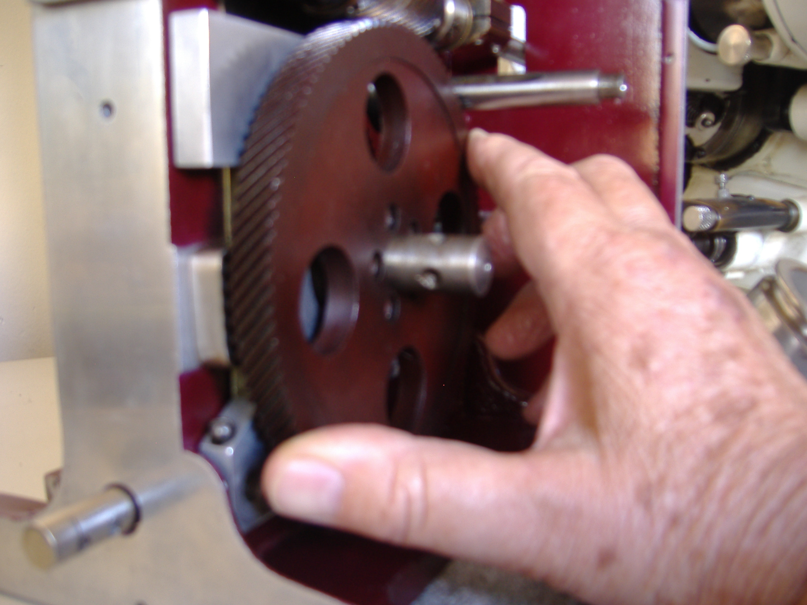
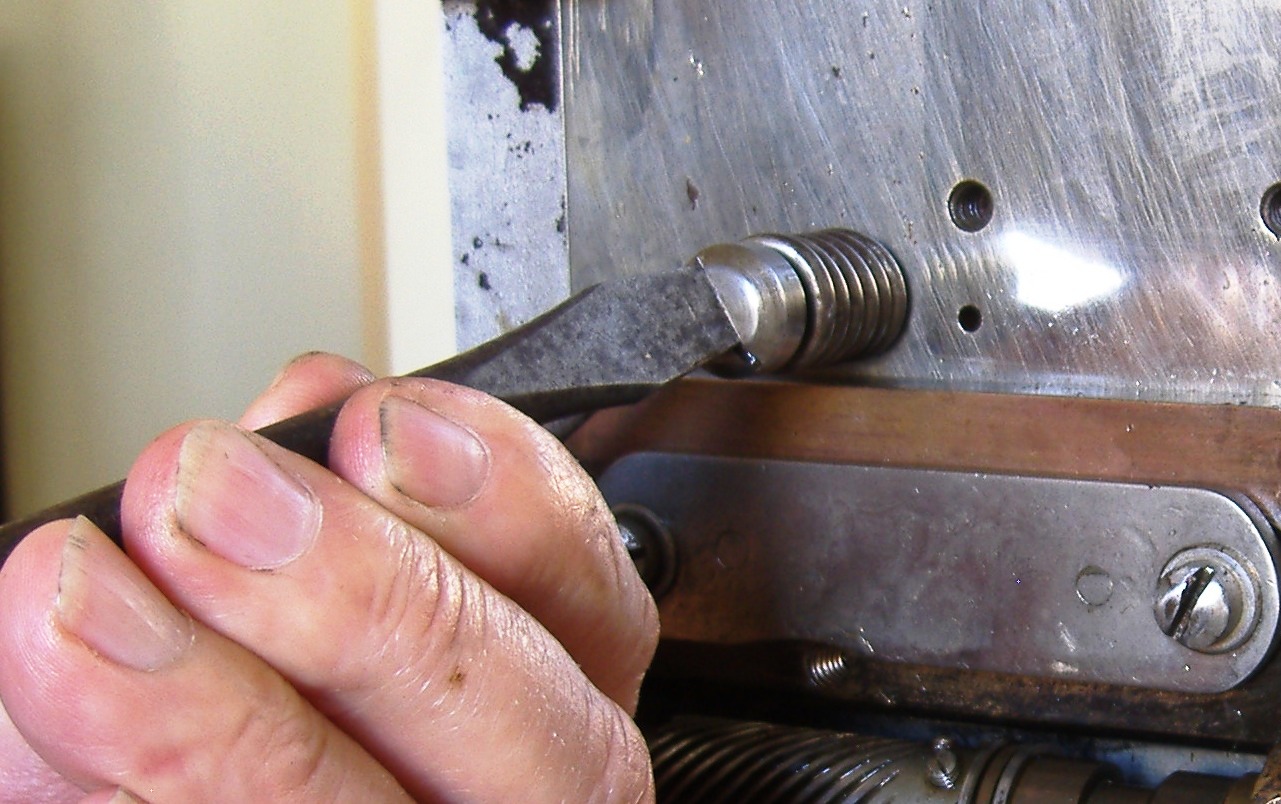
Then Carefully push on the flywheel, engaging its gear to the main gear